

Schlagblech moving device for computer type tricot machine
A technology of moving device and yarn pressing plate, which is applied in warp knitting, textiles, papermaking, knitting, etc., can solve the problems of collision, inconvenient adjustment, unsuitable for high speed, etc., and achieve simple transmission mechanism, simple and compact structure, and transmission route short effect
- Summary
- Abstract
- Description
- Claims
- Application Information
AI Technical Summary
Problems solved by technology
Method used
Image

Examples
Embodiment 1
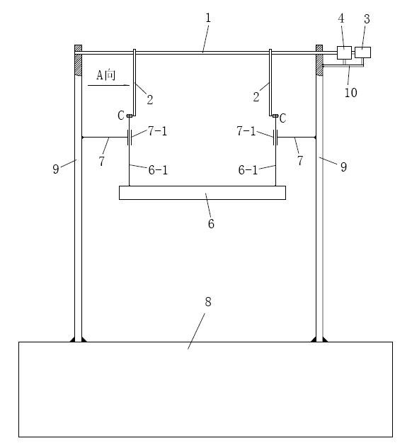
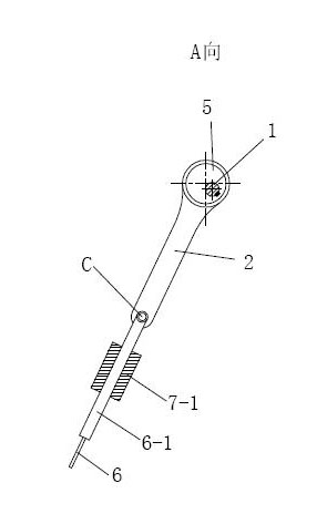
[0015] See figure 1 and figure 2 , embodiment 1 comprises yarn pressing board 6, two wall boards 9 fixed on the left and right sides of warp knitting machine oil tank 8 top surface respectively and the yarn pressing input shaft 1 between the two wall boards 9, the yarn pressing input shaft 1 The two ends of each are respectively inserted in the holes of the two wallboards 9 and are connected in the form of a rotary pair. A support 10 is fixed on the outer surface of one of the wallboards, a servo motor 3 and a speed reducer 4 are installed on the support 10, and the speed reducer 4 is connected with the output shaft of the servo motor 3. The rotation of the servo motor is decelerated by the reducer and the torque is increased to meet the speed of the yarn pressing board and the power requirements of the yarn pressing device. One end of the yarn pressing input shaft 1 extends out of the wallboard and is connected with the output shaft of the speed reducer 4 through a shaft c...
Embodiment 2
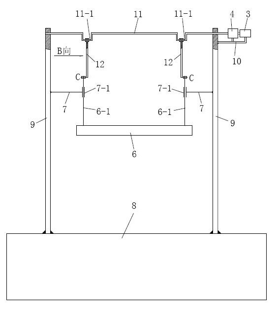
[0018] See image 3 and Figure 4 , embodiment 2 comprises yarn pressing board 6, two wall boards 9 fixed on the left and right sides of warp knitting machine oil tank 8 top surface respectively and the yarn pressing input shaft 11 between the two wall boards 9, the yarn pressing input shaft 11 The two ends of each are respectively inserted in the holes of the two wallboards 9 and are connected in the form of a rotary pair. A support 10 is fixed on the outer surface of one of the wallboards, a servo motor 3 and a speed reducer 4 are installed on the support 10, and the speed reducer 4 is connected with the output shaft of the servo motor 3. One end of the yarn pressing input shaft 11 stretches out from the wallboard and is connected with the output shaft of the speed reducer 4 through a shaft coupling. Each of the two wallboards 9 is fixed with a yarn pressing plate guide 7, and the end of the yarn pressing plate guide 7 is a sleeve 7-1.
[0019] The yarn pressing input sha...
PUM
 Abstract
Description
Claims
Application Information