Maximum power tracking type wind power generation device with energy predicting function and method thereof

A technology of maximum power tracking and wind power generation device, applied in the direction of wind power generation, wind turbine, wind turbine combination, etc., can solve the problems of control lag, inability to realize battery charging current prediction and control, etc., to reduce harmonics and losses, Significant economic and social benefits, the effect of ensuring stable operation and safety

Inactive Publication Date: 2010-08-04
HARBIN INST OF TECH
View PDF3 Cites 36 Cited by
  • Summary
  • Abstract
  • Description
  • Claims
  • Application Information

AI Technical Summary

Problems solved by technology

[0005] The object of the present invention is to provide a maximum power tracking type wind power generation device and method with energy prediction function, which solves the problem that in the existing

Method used


Image

  • Maximum power tracking type wind power generation device with energy predicting function and method thereof
  • Maximum power tracking type wind power generation device with energy predicting function and method thereof
  • Maximum power tracking type wind power generation device with energy predicting function and method thereof

Examples


specific Embodiment approach 1

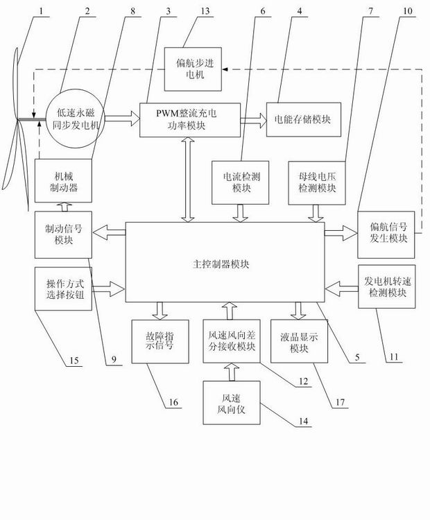
[0027] Specific implementation mode one: the following combination figure 1 Describe this embodiment, this embodiment includes a blade 1, a low-speed permanent magnet synchronous generator 2, a PWM rectification charging power module 3, an electric energy storage module 4, a main controller module 5, a current detection module 6, a bus voltage detection module 7, Mechanical brake 8, brake signal module 9, yaw signal generation module 10, generator speed detection module 11, wind speed and direction differential receiving module 12, yaw stepping motor 13 and wind speed and direction instrument 14; wherein:

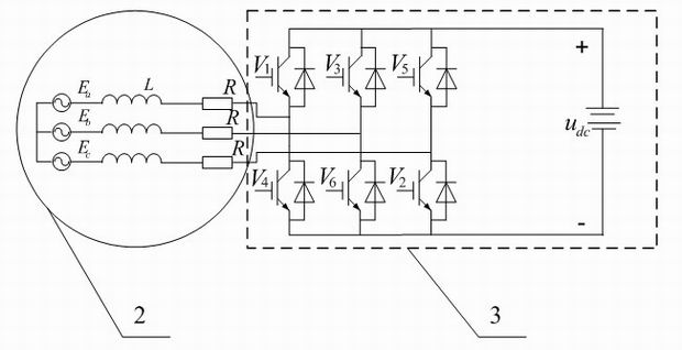
[0028] The blade 1 is coaxially connected with the low-speed permanent magnet synchronous generator 2, and the PWM rectification charging power module 3 is used to rectify the voltage and current output by the low-speed permanent magnet synchronous generator 2, and output it to the electric energy storage module 4 for charging;

[0029] The current detection module 6 collec...

specific Embodiment approach 2

[0038] Specific implementation mode two: the following combination Figure 1 to Figure 11 Describe this embodiment, the power generation method of this embodiment is realized based on the following device, this device includes blade 1, low-speed permanent magnet synchronous generator 2, PWM rectification charging power module 3, electric energy storage module 4, main controller module 5, Current detection module 6, bus voltage detection module 7, mechanical brake 8, brake signal module 9, yaw signal generation module 10, generator speed detection module 11, wind speed and direction differential receiving module 12, yaw stepping motor 13 and wind speed wind vane 14;

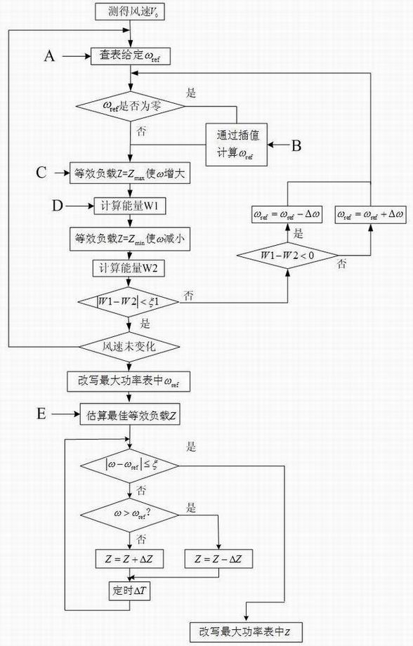
[0039] The process of the power generation method is:

[0040] Step 1, the main controller module 5 judges whether the electric energy storage module 4 is fully charged according to the voltage signal collected by the bus voltage detection module 7, if so, execute step 8; if not, execute step 2;

[0041] Step 2:...


PUM


Abstract

The invention discloses a maximum power tracking type wind power generation device with an energy predicting function and a method thereof, which belong to the field of wind power generation energy conversion, and solve the problems that a low-power wind power generation device and a power generation method delay system control and cannot predict and control the charging current of a storage battery. The device comprises a blade, a low-speed permanent magnet synchronous generator, a PWM rectification charging power module, an electric energy storage module, a main controller module, a current detection module, a busbar voltage detection module, a mechanism brake, a brake signal module, an off-course signal generating module, a generator rotating speed detection module, a wind speed and wind direction difference receiving module, an off-course step motor and an anemoclinograph. The power generation method of the device comprises the following steps of: adjusting the blade according to wind speed signals; controlling the low-speed permanent magnet synchronous generator to realize the tracking of the maximum power; and controlling the PWM rectification charging power module to realize the output of unit power factors of the low-speed permanent magnet synchronous generator. The device and the method are used for wind power generation.

Description

technical field [0001] The invention relates to a maximum power tracking type wind power generation device and method with energy prediction function, and belongs to the field of off-grid wind power generation energy conversion. Background technique [0002] The power generation method of the low-power wind power generation device widely adopted at present all adopts the method of uncontrolled rectification to charge the storage battery. The main problems are: the starting wind speed of the generator is low, the charging performance of the system is unstable, and only when the peak line voltage of the generator is greater than the DC voltage of the battery, the charging characteristics can be shown. It cannot be charged; at the same time, there are defects of charging current distortion and high harmonic content. [0003] On the other hand, the power generation methods adopted by the existing low-power wind power generation devices all adopt tail rudder work. When the momen...

Claims


Application Information

Patent Timeline
IPC IPC(8): F03D9/00F03D7/00H02P9/14F03D9/25F03D17/00
CPCY02E10/723Y02E10/725Y02E10/72
Inventor 赵克孙力杜金明吴凤江孙伟
Owner HARBIN INST OF TECH
Why Eureka
Try Eureka