
Tube coiling/decoiling machine and relative process

A technology of uncoiler and coil, applied in the downstream fields of rolling mills, can solve the problems of reducing output, increasing operator safety risks, increasing labor costs, etc., and achieving the effect of high productivity

Inactive Publication Date: 2010-08-04
达涅利&C.机械股份有限公司
View PDF0 Cites 4 Cited by
  • Summary
  • Abstract
  • Description
  • Claims
  • Application Information

AI Technical Summary

Problems solved by technology

[0012] The deficiency of prior art is: in the process of coiling / uncoiling, need a large amount of manual operations
Reduced output, increased labor costs, and increased operator safety risks

Method used


Image

  • Tube coiling/decoiling machine and relative process
  • Tube coiling/decoiling machine and relative process
  • Tube coiling/decoiling machine and relative process

Examples


Embodiment Construction

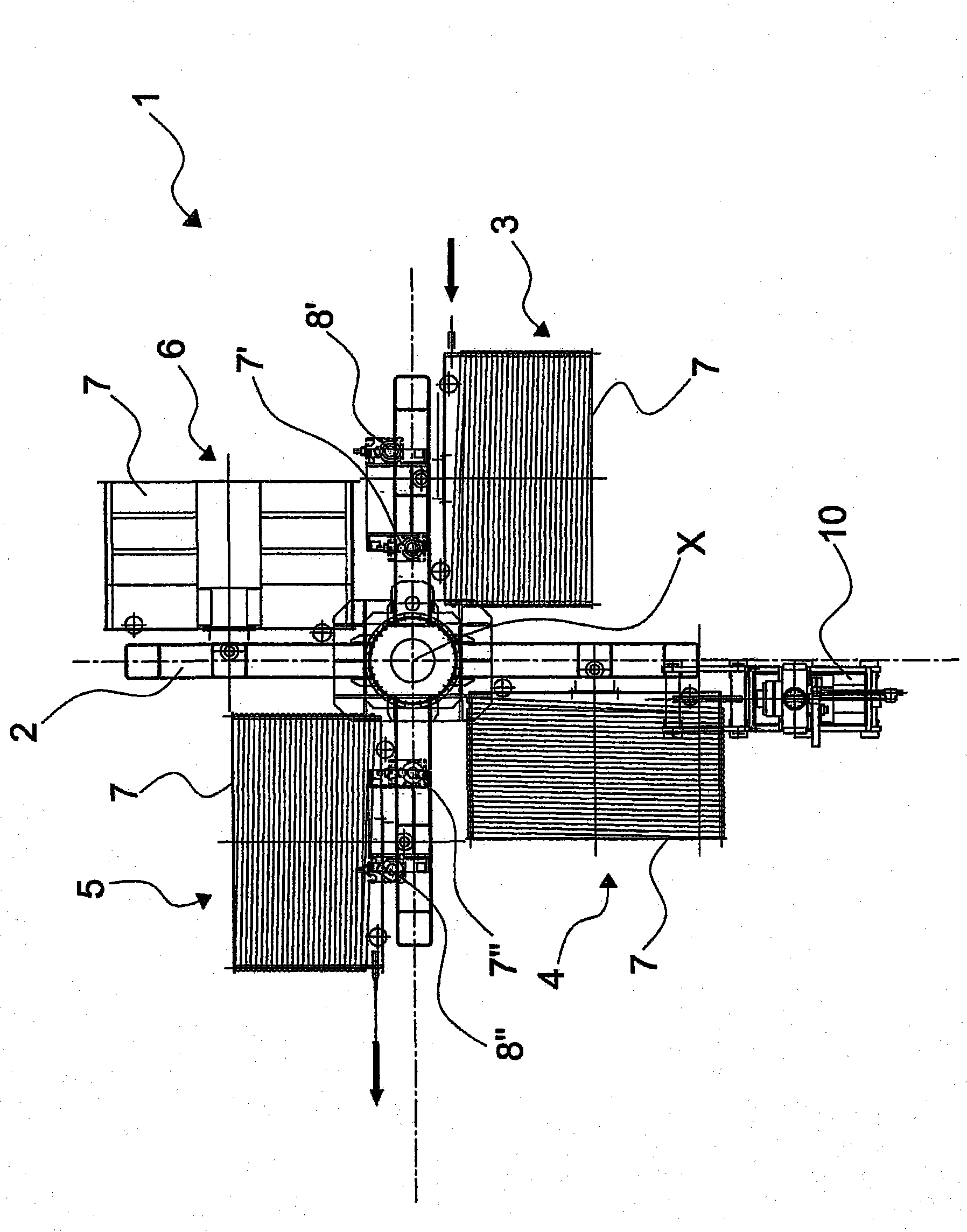
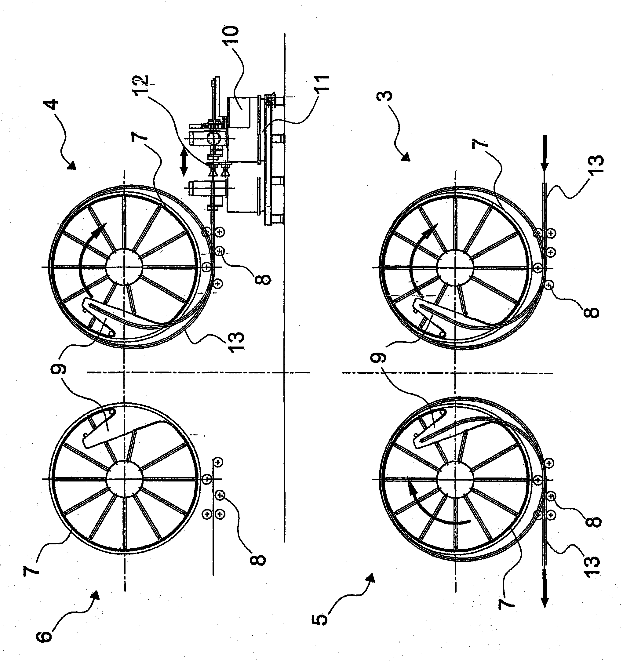
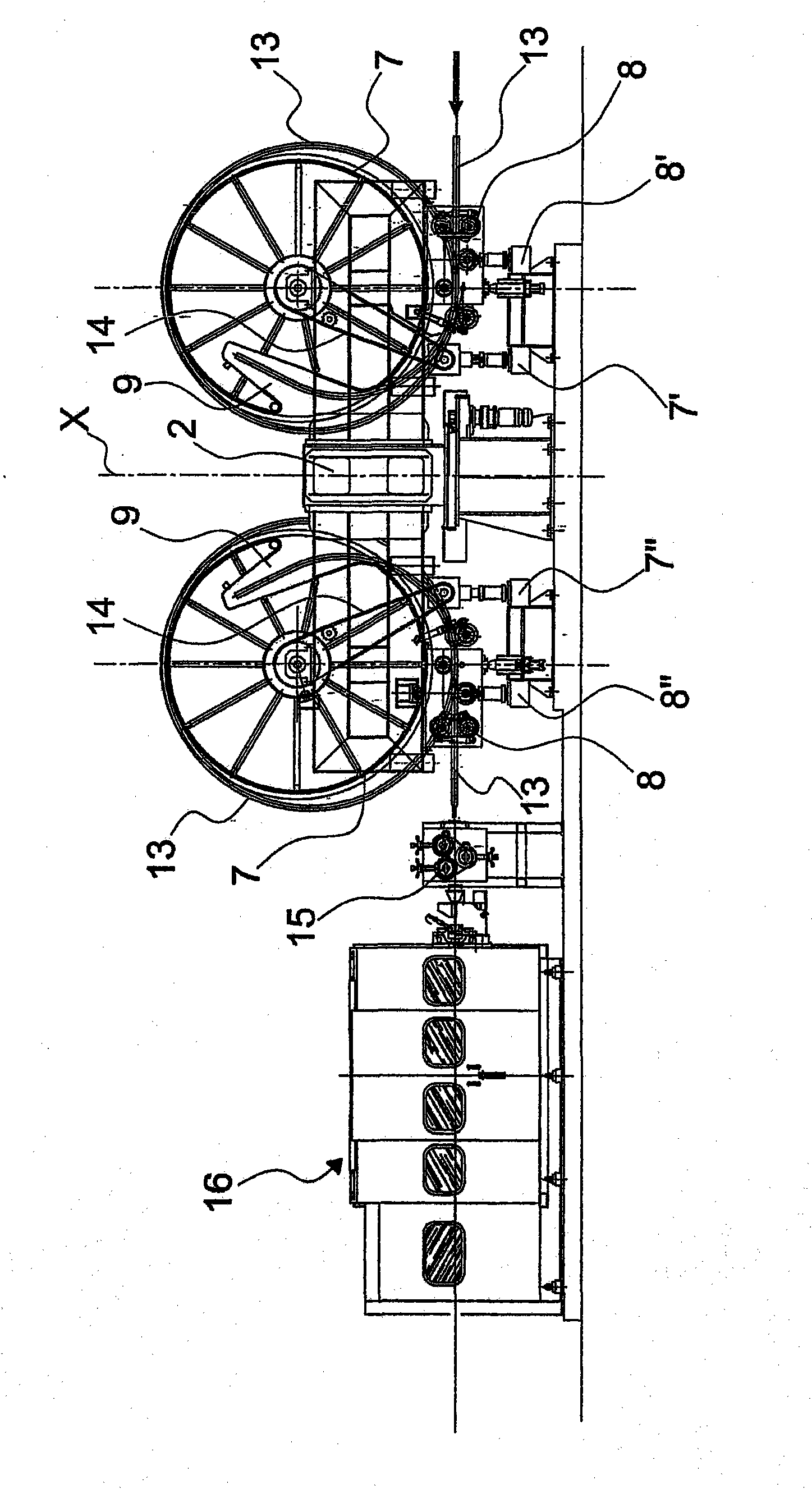
[0032] As shown in the accompanying drawings, according to the coiling / uncoiling machine of the present invention, generally marked 1, it is usually located between the rolling mill (not shown in the figure) and the downstream traction assembly for subsequent processing, and the coiling / uncoiling machine includes A cross-shaped structure 2 and a table corresponding to each arm of the cross-shaped structure.

[0033] These workbenches include:

[0034] - a coiling station 3 for forming coiled tubing;

[0035] - Taper station 4 for tapering one end of the tube;

[0036] - an uncoiling station 5 for uncoiling the conical tube coil;

[0037] - Wait for station 6.

[0038] On each arm of the cross-shaped structure 2 there is a coil support roller 7, under which bending means 8 are integrally fixed.

[0039] The cross-shaped structure 2 can be rotated 90 degrees about its X-axis direction, so that the drum 7 and the bending device 8 can be moved from one station to the other dur...


PUM


Abstract

Tube coiling / decoiling machine, used in particular downstream of a rolling mill, capable of significantly increasing the production rate by automating numerous operations, consequently reducing labour costs. In particular said coiling / decoiling machine comprises a drum (7), suitable for rotating around its longitudinal axis, provided with a cavity (9) for containing the first end of the tube (13) corresponding to a peripheral portion there of. A relative tube coiling / decoiling process more efficient than the one currently used is described.

Description

technical field [0001] The invention relates to a coiling / uncoiling machine for metal pipes and a corresponding method, which can be specifically applied downstream of rolling mills. Background technique [0002] Downstream of a pipe mill that rolls, for example, copper pipe, there is usually a coiler / uncoiler for coiling straight pipe from the mill into coils and supporting the formed coils, which are then uncoiled for downstream drawing. stretch processing. [0003] When the rolled tube has a length greater than 100 meters, it is coiled into a coil weighing at least 500 kg, thus reducing the overall size. The tube material is easily deformed due to the annealing process used in the upstream rolling process. [0004] The coiler / uncoiler has a cross-type structure with two or four coil support tables, each of which is equipped with two motorized rollers with grooves, whose shafts are set horizontally to support the weight of the entire coil . [0005] Between the rolling...

Claims


Application Information

Patent Timeline
IPC IPC(8): B21C47/04B21C47/18B21C47/24B21C47/32
CPCB21C47/18B21C47/245B21C47/04B21C47/323
Inventor 斯蒂芬诺·洛多洛布鲁诺·丘奇
Owner 达涅利&C.机械股份有限公司
Learn More