
Bending double-shaft mechanism

A dual-axis and frame technology, applied in the field of bending dual-axis mechanism, can solve problems such as unfavorable mass production, slow bending speed, broken motor shaft, etc., to prevent axis drift, increase strength, and reduce tube surface. damage effect

Inactive Publication Date: 2010-08-11
HENAN KELONG GRP
View PDF0 Cites 0 Cited by
  • Summary
  • Abstract
  • Description
  • Claims
  • Application Information

AI Technical Summary

Problems solved by technology

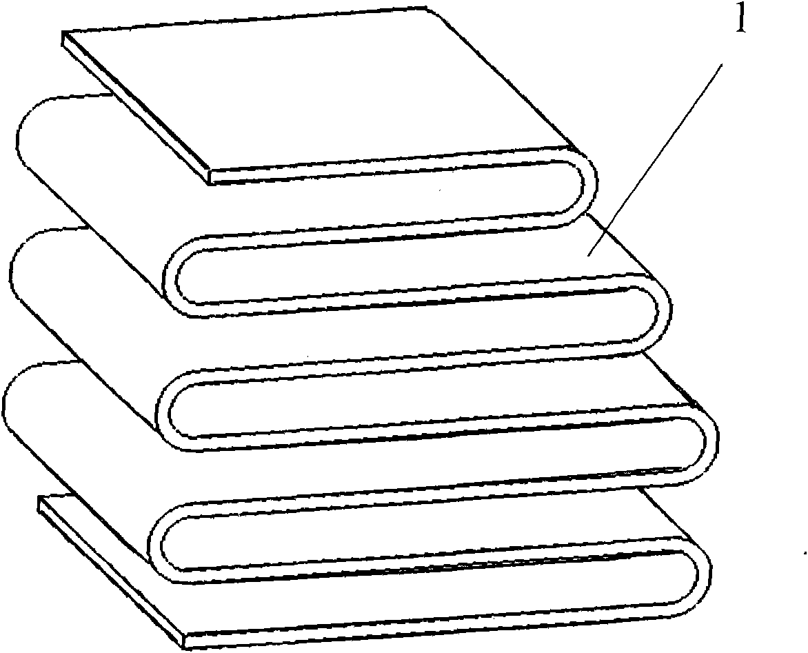
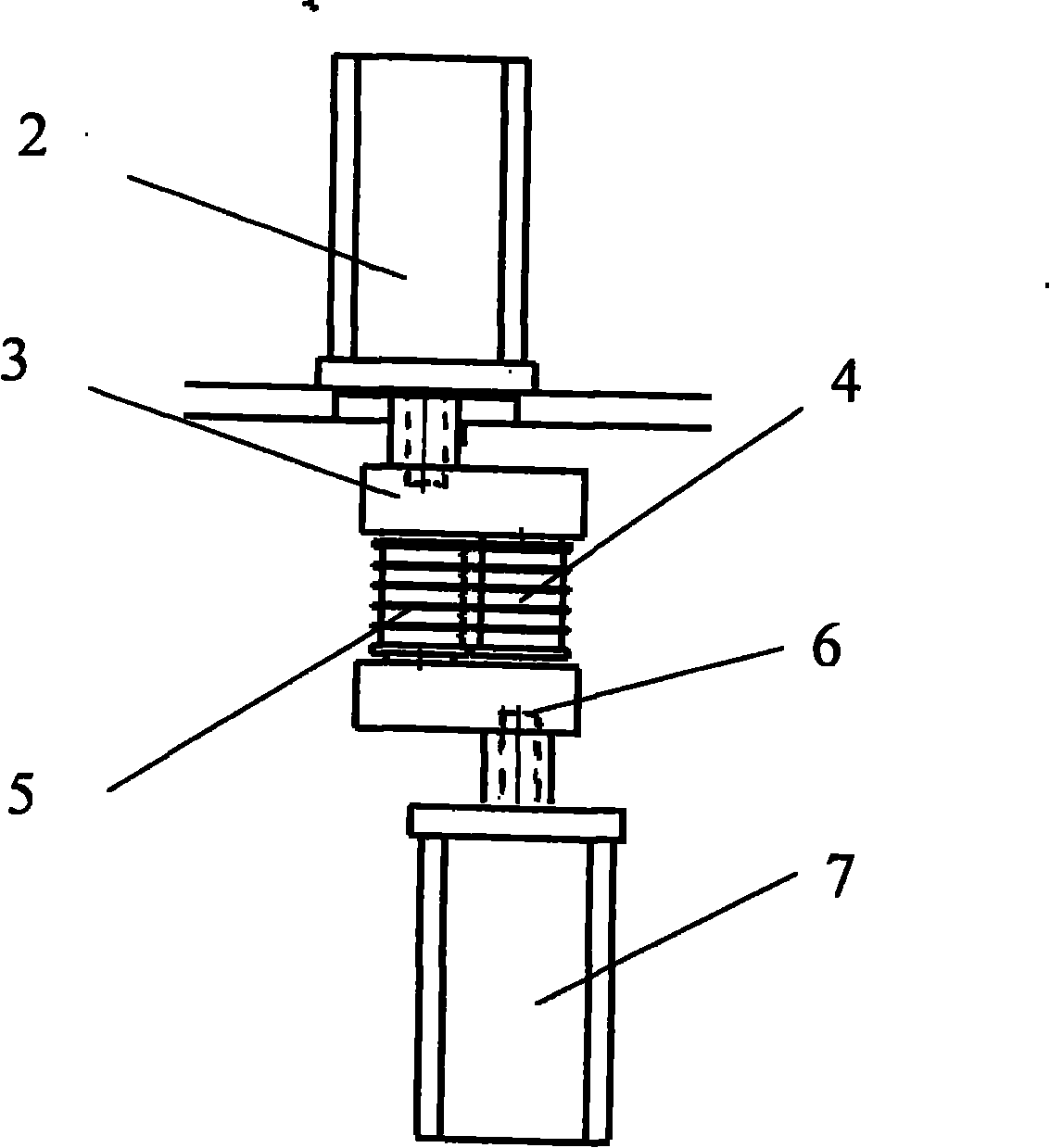
[0002] The S-shaped bending required to be produced is as figure 1 , the existing bending is composed of the upper motor, the upper crank 3, the left bending shaft 4 to form the left bending assembly, the lower motor 7, the lower crank 6, and the right bending shaft to form the right bending assembly. , it is possible to break the motor shaft, so it can only be used for a small amount of pipe bending (called coil pipe in the industry), not competent figure 1 Bending of the sheet (slat-like) shown
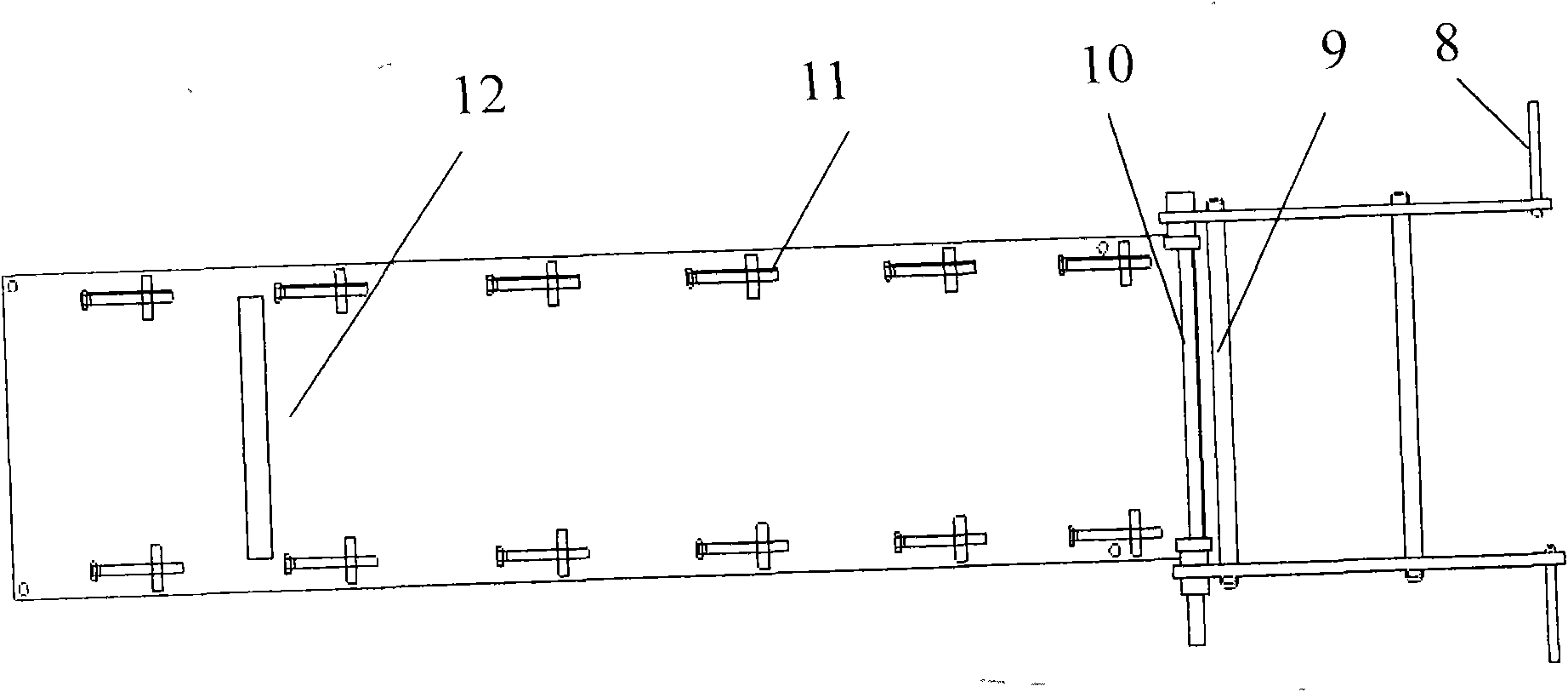
(See figure 2 ), the manual bending is performed by clamping plate 12 to position the workpiece, after penetrating into the inner bending shaft 10, the hand push plate drives 8 to drive the bending shaft 9 to bend once, and then withdraws from the inner bending shaft 10, and the workpiece is rotated 180 degrees with the clamping plate 12 Locate the next position and start the next bending (see image 3 ), its disadvantages are: physical effort, slow bending speed, not conducive to mass production

Method used


Image

  • Bending double-shaft mechanism
  • Bending double-shaft mechanism
  • Bending double-shaft mechanism

Examples


Embodiment Construction

[0007] Embodiments are described in detail with reference to the above drawings. Figure Descriptions 1 to 12 have been described in the background technology and will not be described again. The lower part of the biaxial 18 has a positioning step 18, the distance block 16 is welded on the positioning step of the biaxial, the needle bearing 15 is set on the biaxial 17 and is limited by the positioning step, and the top of the biaxial is equipped with a clamp Block 13 clamps the biaxial by screw 14, (see Figure 4 , 5 ), the shaft member is made up of twist block 20, shaft block 21, motor shaft head 22, (see Figure 6 , 7 , 8) Axle block 21 is placed in the motor shaft head 22, and the motor shaft head is installed in the square groove of twist block 29, and biaxial installation hole 19 is arranged on the twist block, and the lower end of double shaft 17 is put into double shaft after spring 23. Shaft installation hole 19, when the motor shaft head is aligned with the right ...


PUM


Abstract

The invention discloses a bending double-shaft mechanism. The invention aims at providing a bending double-shaft mechanism which can realize the mass production and fast bending speed and is free from requiring physical power, which comprises a bending motor, a servo motor, a stander and a bracket, wherein the lower ends of the two shafts are provided with a distance block, a needle bearing is sleeved on the two shafts, the top parts of the two shafts are provided with clamping block which clamps the two shafts through screws, a left and a right air cylinders are fixed on a crossbeam above the two shafts, an axis block is arranged inside a motor shaft head, the motor shaft head is installed inside a square groove of a twisting block, the twisting block is provided with holes for holding the two shafts, the twisting block is horizontally arranged on a supporting plate, the bending motor is fixed on a motor plate, two slide shaft sleeves are welded on the motor plate, a transposition air cylinder is fixed on the bracket, the servo motor is installed on one end of a trough plate, the other end of the trough plate is fixed on the supporting plate, a ball screw is installed inside the trough plate and is connected with the servo motor through a coupler, and a feeding platform is fixed on a rolling nut behind the stander.

Description

Technical field: [0001] The invention relates to a bending biaxial mechanism, which is suitable for coil bending processing equipment for manufacturing condensers in the refrigerator industry, and is used for processing S-shaped plates and pipes with similar shapes. Background technique: [0002] The S-shaped bending required to be produced is as figure 1 , the existing bending is composed of the upper motor, the upper crank 3, the left bending shaft 4 to form the left bending assembly, the lower motor 7, the lower crank 6, and the right bending shaft to form the right bending assembly. , it is possible to break the motor shaft, so it can only be used for a small amount of pipe bending (called coil pipe in the industry), not competent figure 1 Bending of the sheet (lath-like) shown. (See figure 2 ), the manual bending is performed by clamping plate 12 to position the workpiece, after penetrating into the inner bending shaft 10, the hand push plate drives 8 to drive the b...

Claims


Application Information

Patent Timeline
Patent Type & Authority Applications(China)
IPC IPC(8): B21D11/06
Inventor 王在中
Owner HENAN KELONG GRP
Learn More