
Double anchoring section prestressed anchoring system with three-layer protection and anchoring method thereof

A double-anchored, prestressed technology, applied in the direction of excavation, climate change adaptation, sheet pile walls, etc., can solve the problems of reducing the overall stability of the original reinforced structure, changing the mechanical state of rock and soil, and loss of prestressing, so as to achieve long-term maintenance The effect of stabilization, reduction of prestress loss, enhancement of stability and durability

Active Publication Date: 2010-08-11
UNIV OF SCI & TECH BEIJING
View PDF6 Cites 32 Cited by
  • Summary
  • Abstract
  • Description
  • Claims
  • Application Information

AI Technical Summary

Problems solved by technology

[0007] (1) For the permanent anchorage system, especially the anchorage system used in large-scale and key projects, such as the slope reinforcement of large-scale hydropower stations, etc., its effective service period is as long as a hundred years, and the surface rock and soil near the anchor head is affected by the external environment. The influence of factors is large, including weathering, rheological effect of rock and soil mass, corrosion, etc., which will cause a large loss of prestress, thereby reducing the overall stability of the original reinforced structure
[0008] (2) The impact force generated by factors such as rolling stones, blasting vibrations and earthquakes will significantly change the mechanical state of the rock and soil near the anchor head, resulting in significant loss of prestress
[0009] (3) Small surface rock and soil deformation can produce a large prestress loss

Method used


Image

  • Double anchoring section prestressed anchoring system with three-layer protection and anchoring method thereof
  • Double anchoring section prestressed anchoring system with three-layer protection and anchoring method thereof
  • Double anchoring section prestressed anchoring system with three-layer protection and anchoring method thereof

Examples


Embodiment Construction

[0047] The technical solution of the present invention will be further described below in conjunction with the accompanying drawings.

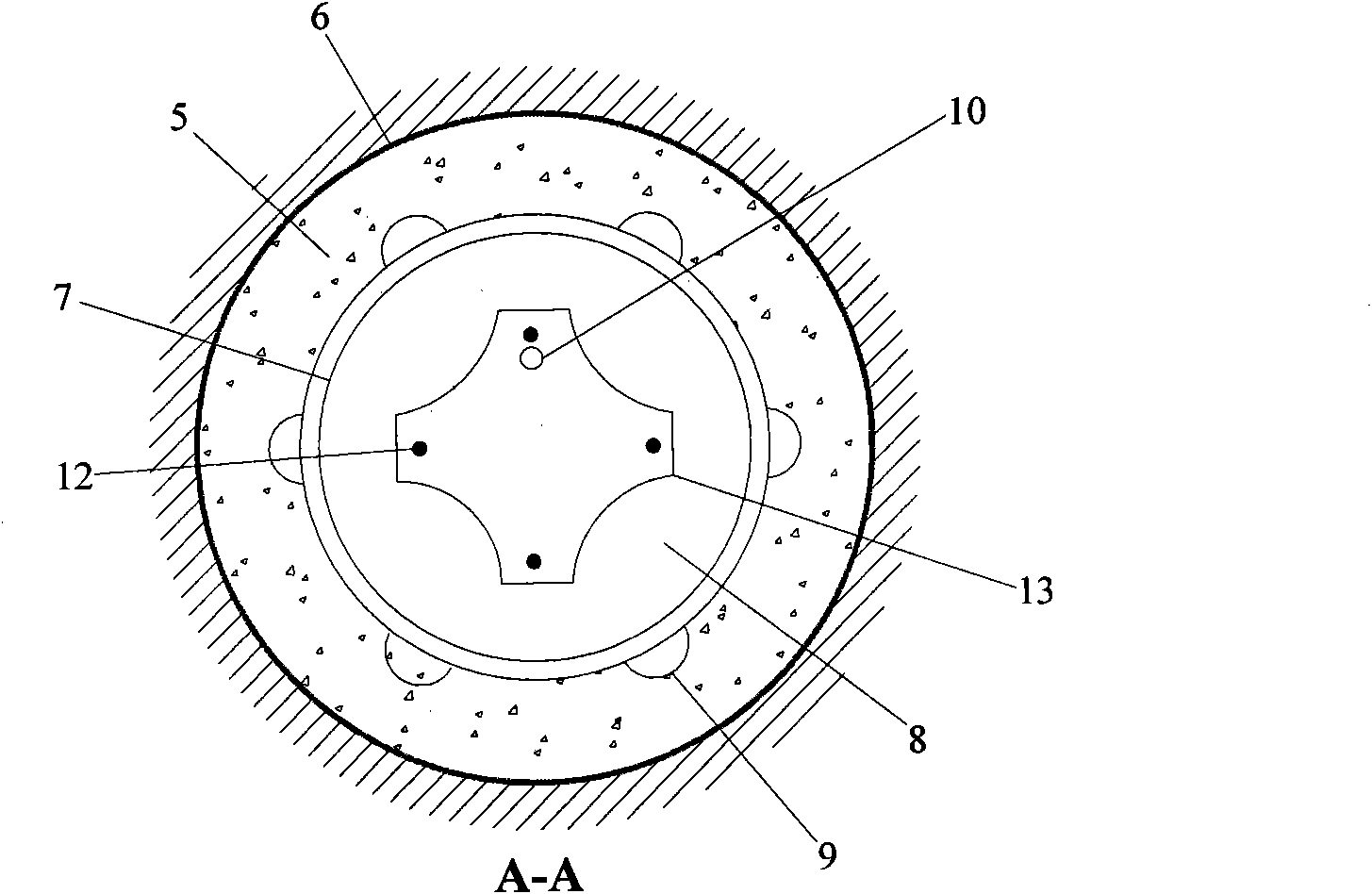
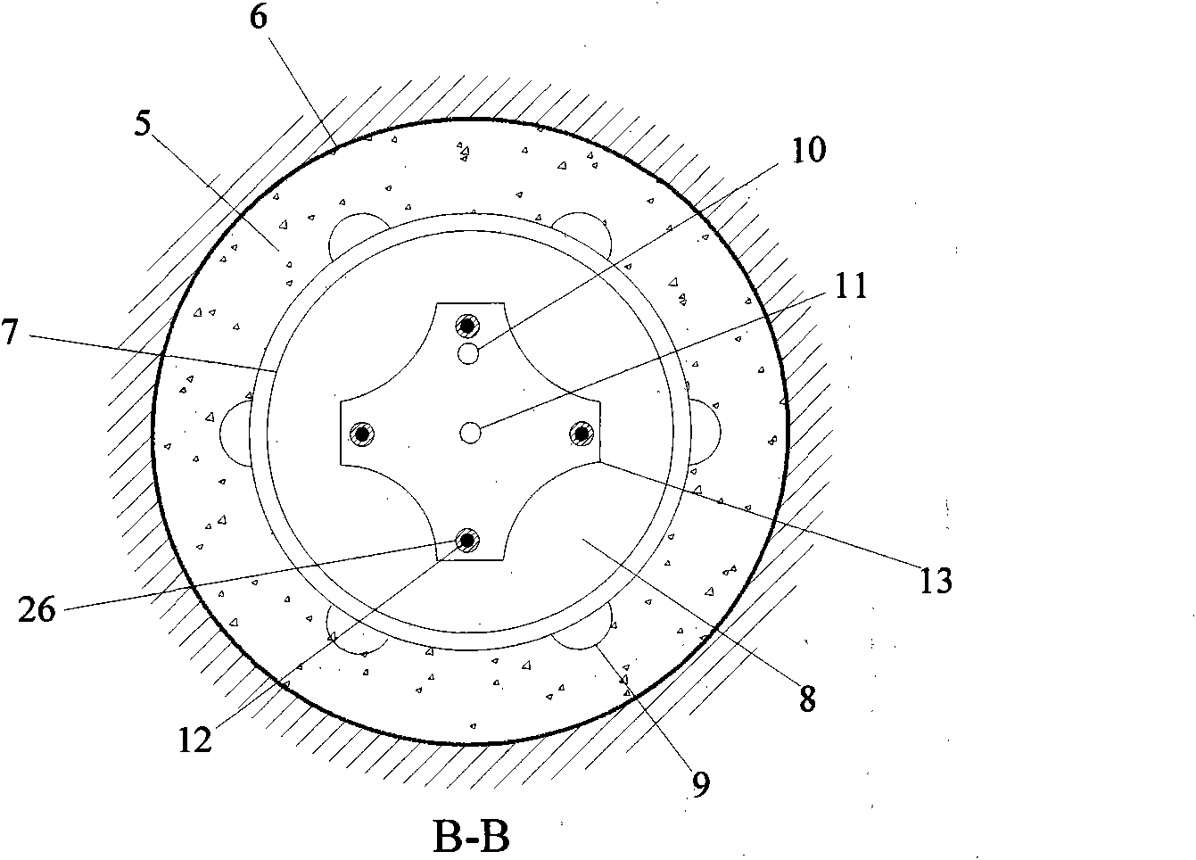
[0048] Such as figure 1 As shown, a structural diagram of a prestressed anchoring system and anchoring method with three layers of protection and double anchorage sections of the present invention. The present invention is a prestressed anchoring system with three layers of protection and double anchoring sections, comprising an inner anchoring section, a free section, an outer anchoring section, a prestressed tendon and an anchor head section.

[0049] The anchor head section 4 is composed of an anchor pier 21 , a backing plate 19 , an anchor 18 and a protective cap 20 . The anchor 18 is fixed on the backing plate 19, and the backing plate 19 is fixed on the outer end of the shallow rock and soil mass 22 through the anchor pier 21; the inner anchoring section 1, the free section 2 and the outer anchoring section 3 are located in the bellows ...


PUM


Abstract

The invention relates to a double anchoring section prestressed anchoring system with three-layer protection and anchoring method thereof. The anchoring system is composed of an inner anchoring section, a free section, an outer anchoring section and an anchor section. Outer layer binder, corrugated pipe and inner layer binder form three-layer protection for the inner and outer anchoring sections of the anchoring system, the outer layer binder, the corrugated pipe, a sleeve and the inner binder form four-layer protection for the free section, thus greatly improving resistance to corrosion of anchoring structure. Double anchoring sections form an anchoring force holding end and a prestress holding end. Compared with common single anchoring section anchoring method, the invention has the advantages that the outer anchoring section in specific design can effectively inhibit influence of creep, weathering, corrosion, blasting and earthquake of mantle rock soil body on anchoring system and the aim of avoiding or reducing prestress loss can be achieved. The invention has simple implementation and strong operability, procedure change is less compared with the existing anchoring method, and the invention has obvious advantage compared with the permanent anchoring system and can be applicable to reinforcement of geotechnical engineering such as side slope and foundation pit.

Description

technical field [0001] The invention belongs to the field of geotechnical engineering support and reinforcement, and in particular relates to a prestressed anchorage system with three-layer protection and double anchorage sections for reinforcement of slopes, foundation pits, roadways, chambers, etc. and an anchoring method thereof. technical background [0002] Prestressed anchoring is the general term for prestressed rock anchors and concrete prestressed anchors [On the application and development of prestressed anchorage technology in my country's water conservancy and hydropower projects, Wang Hongxia; Wang Jianing; Journal of North China Institute of Aerospace Industry, 2003.01], is an anchoring technology developed on the basis of prestressed concrete. It can apply active precompression stress to bedrock or buildings in advance according to the direction, size and anchorage depth required by the design, so as to achieve the purpose of strengthening or improving its str...

Claims


Application Information

Patent Timeline
Patent Type & Authority Applications(China)
IPC IPC(8): E02D5/74E02D17/02E02D17/20E04C5/08E04C5/10E04G21/12
CPCY02A10/23
Inventor 吴顺川高永涛
Owner UNIV OF SCI & TECH BEIJING
Learn More