Parallel detecting system of rollers

A parallel detection and detector technology, applied in the field of detection systems, can solve problems such as low-cost detection systems, and achieve the effects of accurate detection, simple structure, and easy operation

Active Publication Date: 2010-08-11
洪田科技有限公司
View PDF0 Cites 7 Cited by
  • Summary
  • Abstract
  • Description
  • Claims
  • Application Information

AI Technical Summary

Problems solved by technology

[0005] At present, there is no detection system that can accurately...

Method used


Image

  • Parallel detecting system of rollers
  • Parallel detecting system of rollers
  • Parallel detecting system of rollers

Examples


Embodiment Construction

[0042] In order to make the technical means, creative features, objectives and effects achieved by the present invention easy to understand, the present invention will be further elaborated below in conjunction with specific diagrams.

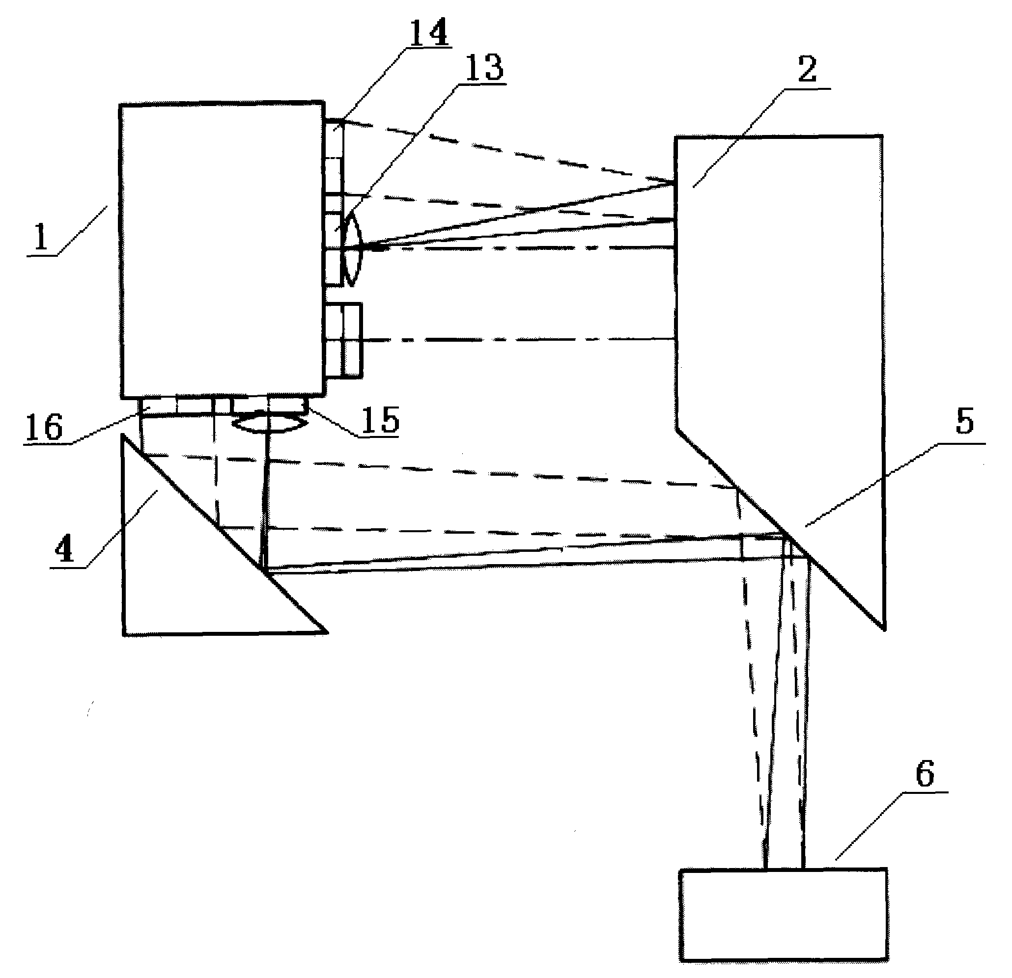
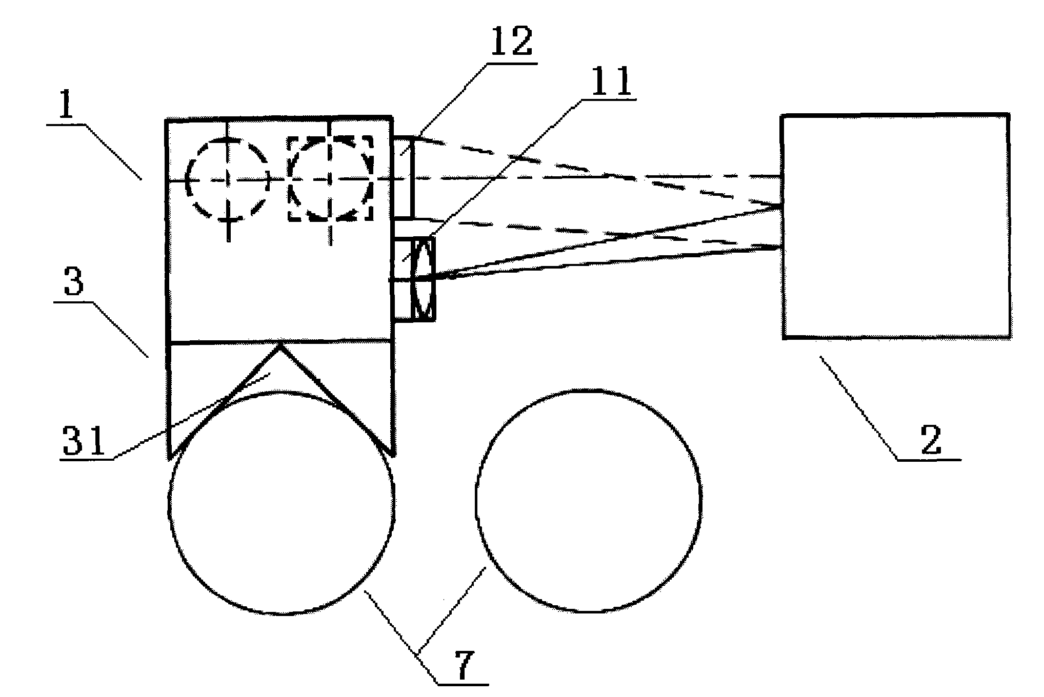
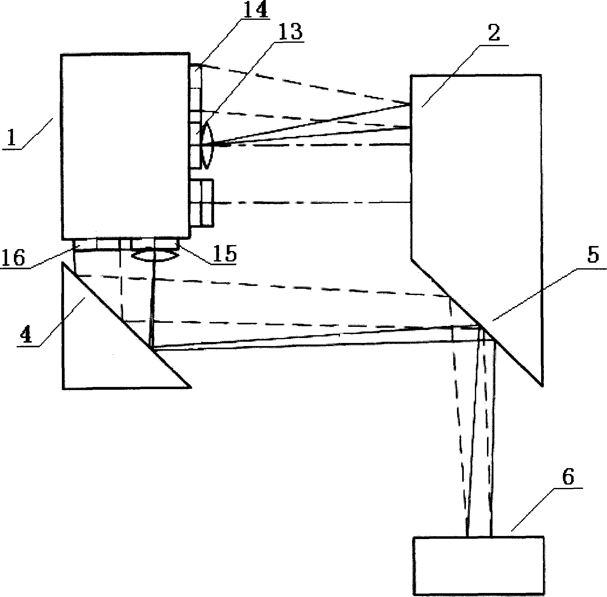
[0043] refer to figure 1 , figure 2 , the roller parallel detection system, including a parallel detector 1 for placing on the roller 7; also includes a reference mirror 2 fixed in front of the parallel detector 1, placed in a vertical direction; the parallel detector 1 includes a laser emitting Direction is towards the first inline laser 11 ahead, and the inline laser emitted is a vertical inline laser; Parallel detector 1 also includes the first optical sensor 12, the first optical sensor 12 and the first inline laser The linear lasers 11 are arranged vertically, and the photosensitive surface of the first optical sensor 12 faces forward; the first optical sensor 12 can be located above or below the first inline linear laser 11; the first o...


PUM


Abstract

The invention relates to the field of mechanical manufacture, in particular to a detecting system. A parallel detecting system of rollers comprises a parallel detector for being placed on rollers. The parallel detecting system of rollers also comprises a reference reflecting mirror, wherein the reference reflecting mirror is fixed in front of the parallel detector and placed in the vertical direction; the parallel detector comprises a first horizontal linear laser the laser emitting direction of which faces to the front, and the emitted horizontal linear laser is vertical horizontal linear laser; the parallel detector also comprises a first optical sensor, the first optical sensor and the first horizontal linear laser are longitudinally arrayed, and the light sensing surface of the first optical sensor faces to the front; and the first optical sensor can be positioned above or below the first horizontal linear laser and is connected with a signal processing module. By adopting the technical scheme, the invention can be applied to the parallel calibration of a plurality of rollers with different heights and has the obvious advantages of simple structure, accurate detection, simple and convenient operation, and the like.

Description

technical field [0001] The invention relates to the field of mechanical manufacturing, in particular to a detection system. Background technique [0002] Rolls are used on many production equipment, and two or even more rolls are used on many production equipment. Many production equipment require these rollers to be parallel to each other, and the precision of parallelism is often very high. Such equipment as papermaking equipment, metal foil production equipment, etc. [0003] With the development of the electronics industry, the amount of circuit boards is increasing. A large amount of copper foil is used in the production process of circuit boards. The quality of copper foil will affect the quality of the circuit board. Therefore, copper foil production equipment is a kind of production equipment that requires high parallel precision of rollers in metal foil production equipment. [0004] For papermaking equipment, metal foil production equipment, especially copper ...

Claims


Application Information

Patent Timeline
IPC IPC(8): G01B11/26
Inventor 陈孟珪
Owner 洪田科技有限公司
Why Eureka
Try Eureka