Wireless heat meter based on ZigBee technology

A heat meter and wireless technology, which is applied in the field of wireless heat meter devices, can solve the problems of long transmission wires, low confidentiality and security, and cannot prevent malicious theft of hot water, etc., and achieves convenient installation and use, anti-electromagnetic The effect of interference and prevention of malicious misappropriation

Inactive Publication Date: 2010-08-11
陈建明 +6
View PDF0 Cites 6 Cited by
  • Summary
  • Abstract
  • Description
  • Claims
  • Application Information

AI Technical Summary

Problems solved by technology

[0003] At present, the installation method of the two temperature sensors of the usual heat meter is unreasonable. It is necessary to install a specific tube press head, and the transmission wire is long, and the interference and signal attenuation are serious. It is necessary to add a drive circuit and an anti-interference circuit.
The temperature sensor is outside the heating meter, so the confidentiality and security are not high, and the heating meter is easy to be maliciously modified
On the other hand, the main structure is a single-channel type, which cannot realize the detection of the return water (heating air) flow rate, and cannot prevent malicious theft of hot water by users, thus causing losses to the heating company

Method used


Image

  • Wireless heat meter based on ZigBee technology
  • Wireless heat meter based on ZigBee technology
  • Wireless heat meter based on ZigBee technology

Examples


Embodiment Construction

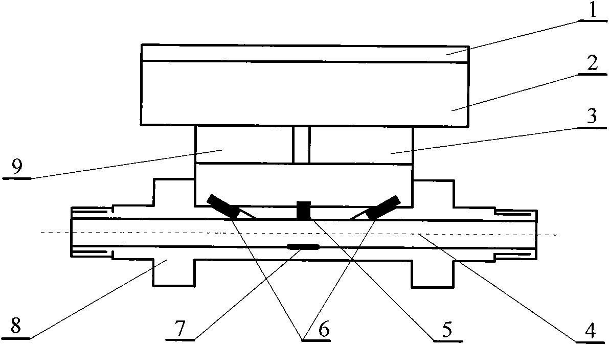
[0012] Such as figure 1 As shown, the device consists of LCD liquid crystal display, ZigBee controller, reflective ultrasonic flowmeter, temperature sensor and battery. The size is determined by the diameter of the selected flowmeter pipe. The overall dimensions of this example are 100mm×65mm×50mm, and the normal flow rate is 1.5m3 / h.

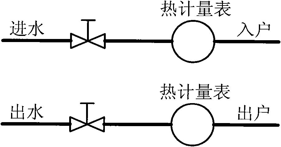
[0013] see figure 1 , the reflective ultrasonic flowmeter (4) of this device is connected in series in the middle of the water inlet (or water outlet) pipeline, the flowmeter adopts a V-shaped reflective structure, and consists of an ultrasonic return device (6), a reflector (7) and Pipe fittings (8) form. The lithium battery for power supply (9) and the communication interface (3) are placed in the lower part of the upper shell of the flowmeter, and the ZigBee controller (2) is placed in the upper part of the shell. deal with. The LCD liquid crystal display (1) is placed on the top of the housing, and is hingedly connected with the lower ...


PUM


Abstract

The invention discloses a heat metering device for cold water and hot water, which realizes that bidirectional flow for water inflow and backwater is detected, a temperature signal and a flow signal are wirelessly transmitted without external connection leads, and operations of wireless charging and wireless meter reading can be carried out. The wireless heat meter is suitable for cold water and hot water. The heat metering device is provided with a reflection ultrasonic flow meter, a temperature sensor, a Zigbee controller and an LCD liquid crystal display device. The reflection ultrasonic flow meter is connected in series in a water inlet (or backwater) pipeline; the temperature sensor is arranged inside the flow meter; the Zigbee controller is arranged on the upper part of the flow meter; and the LCD liquid crystal display device is arranged on the top of the flow meter. Hardware, circuits and software of two devices which are matched to use are all same, the software firstly automatically sets a device connected with a high-temperature pipe to be a master node mode, and sets a device connected with a low-temperature pipe to be an auxiliary node mode when the two devices are used, the two modes can be regularly switched, the faults are automatically switched and a double-controller is simultaneously operated in parallel. The heat metering device for cold water and hot water is suitable for severe environment, such as strong electromagnetic interference, high voltage, high temperature, high humidity and the like, and is widely applied to a cold water / hot water concentrated air-conditioner heating system, thereby realizing separate metering for one meter each household.

Description

[0001] Involved areas [0002] The invention relates to a wireless heat meter device based on ZigBee technology, which is applied to heat measurement. It is especially suitable for cold and hot water centralized air conditioning and heating systems in offices, residences and other places, realizing separate metering for one household and one meter. Background technique [0003] At present, the installation method of the two temperature sensors of the usual heat meter is unreasonable. It needs to install a specific tube press head, and the transmission wire is long, and the interference and signal attenuation are serious. It is necessary to add a drive circuit and an anti-interference circuit. The temperature sensor is outside the heating meter, so the confidentiality and security are not high, and the heating meter is easily modified maliciously. On the other hand, the main structure is a single-channel type, which cannot realize the detection of the return water (heating air...

Claims


Application Information

Patent Timeline
Patent Type & Authority Applications(China)
IPC IPC(8): G01K17/12G08C17/02
Inventor 陈建明王亭岭孙标谭联曹文思王成凤王成龙
Owner 陈建明
Why Eureka
Try Eureka