Induction heating method

A technology of induction heating and induction voltage, applied in induction heating, induction heating device, electric/magnetic/electromagnetic heating, etc., can solve problems such as loss

Inactive Publication Date: 2010-08-11
泽奈基电力公司
View PDF1 Cites 21 Cited by
  • Summary
  • Abstract
  • Description
  • Claims
  • Application Information

AI Technical Summary

Problems solved by technology

Due to this time-varying reverse induced voltage, not a time-constant current, but a time-varying current, flows through the superconducting winding, resulting in undesired losses, the so-called back or reverse induction loss

Method used


Image

  • Induction heating method
  • Induction heating method
  • Induction heating method

Examples


Embodiment Construction

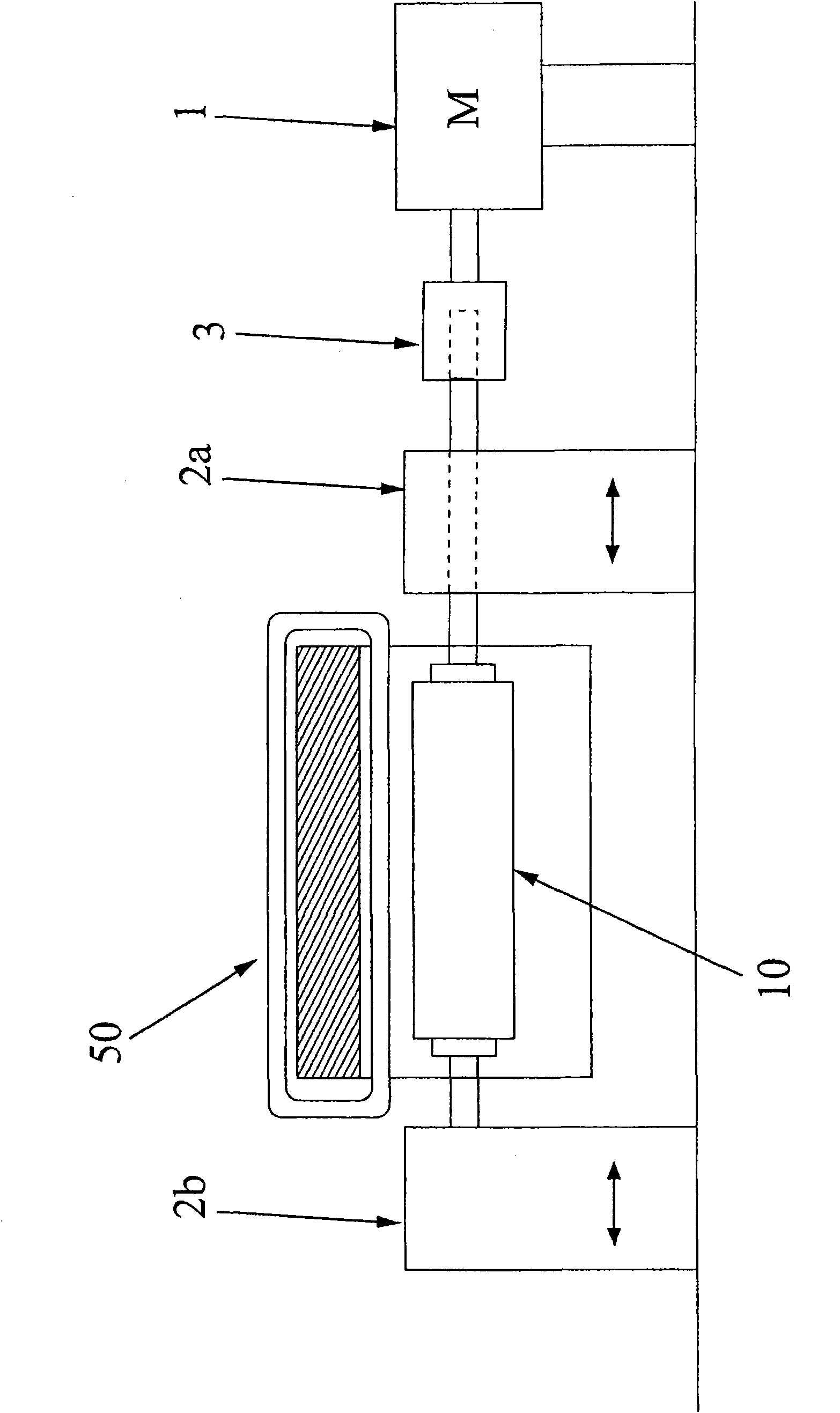
[0035] figure 1 The induction heater of ® is used to heat the blank 10 by rotating the blank 10 in the magnetic field generated by the magnet system 50 . To this end, a blank 10 is clamped between the right-hand and left-hand pressure elements 2a and 2b of the clamping device and driven in rotation by the electric motor 1 . A gear transmission 3 connects the motor shaft to the shaft of the gripper 2a adapted to slide in the direction of the double arrow.

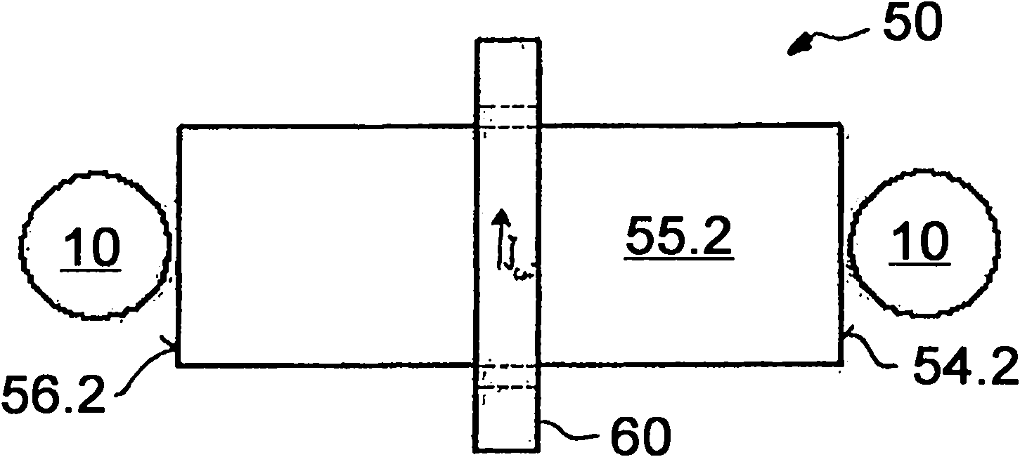
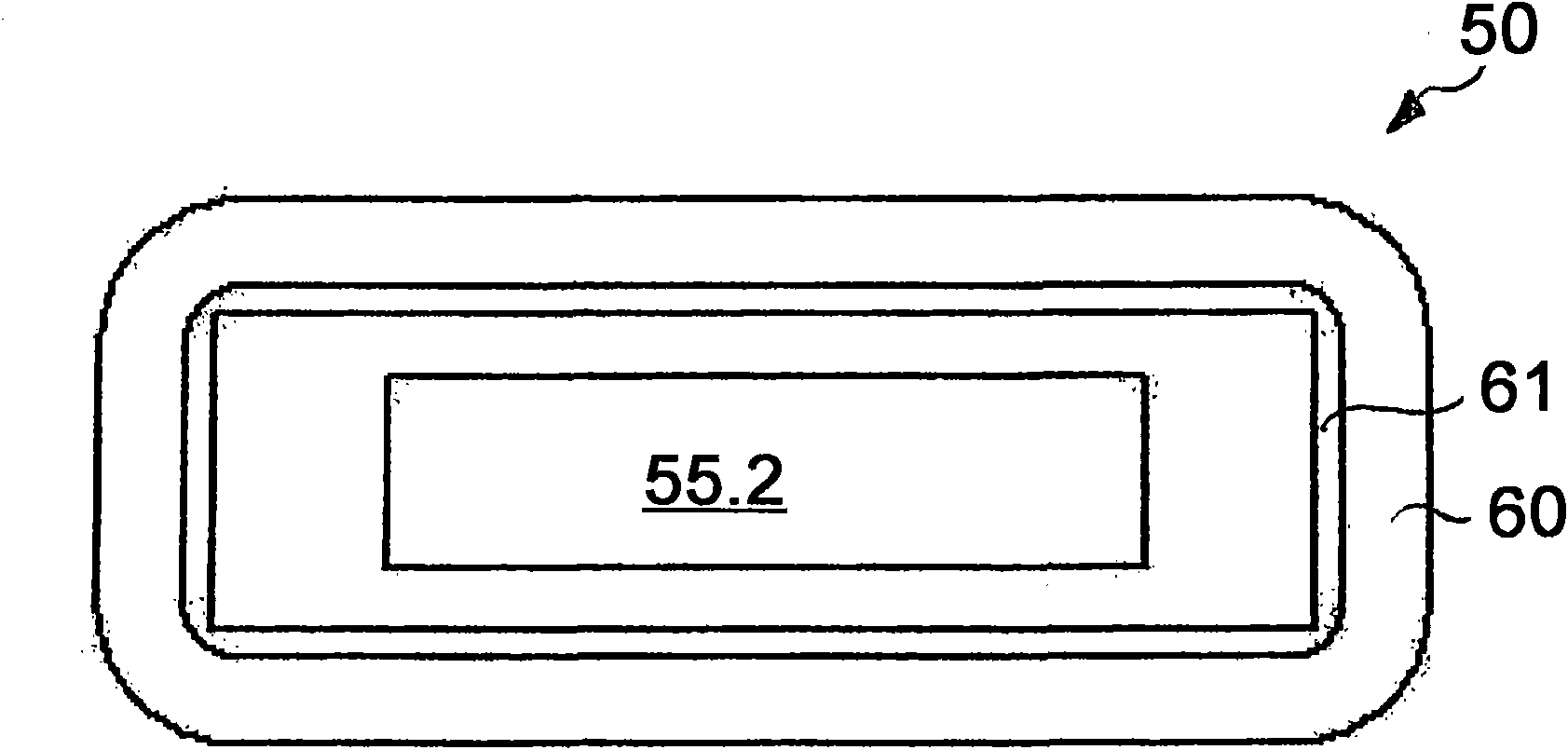
[0036] as in Figure 2a and 2b Shown in a very simplified manner in , the magnet system 50 may comprise a DC-fed superconducting winding 60 on a bar core 55.2. Between the winding 60 and the iron core 55.2, an isolation element 61 is provided, such as an evacuated hollow space, which can reduce the heat entering the winding 60 (only in the Figure 2b shown in ). The rod-shaped iron core 55.2 conducts the magnetic field (not shown) generated by the DC-fed winding 60, which emanates from the two end faces 56.2 and 57.2 of...


PUM


Abstract

When a billet of an electrically conductive material is inductively heated by rotation of the billet (10) relative to a magnetic field, which is produced by means of at least one superconducting winding (60), through which direct-current flows, on an iron core (55.2, 55.3, 55.4), the back-induction voltage can be reduced by producing and maintaining a direct current in the winding (60), with a direct-current value which produces a magnetic flux density in the iron core, at least in the area of the winding, for which flux density the relative permeability of the material of the iron core is less than when no current is flowing through the winding.

Description

technical field [0001] The invention relates to a method for inductively heating a blank of electrically conductive material by relative movement, in particular induced rotation, between the blank and a magnetic field generated by at least one DC-fed superconducting winding on an iron core. Background technique [0002] DE 10 2005 061 670.4 shows such a method. To carry out the method, for example, a cylindrical blank clamped in a gripper driven in rotation can be rotated at a constant number of revolutions about its cylindrical axis in a magnetic field, wherein the magnetic field is induced by a constant current through a superconducting winding. produced. A substantially constant current is thereby induced in the blank. In practice, however, often the blank is not optimally cylindrical, and / or not tightly clamped, so that it does not rotate about its cylindrical axis. Consequently, the magnetic flux through the blank varies, thereby inducing a non-constant amount of ind...

Claims


Application Information

Patent Timeline
Patent Type & Authority Applications(China)
IPC IPC(8): H05B6/02H05B6/14
CPCH05B6/145
Inventor C·菲尔比尔I·哈恩C·比勒
Owner 泽奈基电力公司
Why Eureka
Try Eureka