
Blast furnace cooling structure

A cooling structure and blast furnace technology, applied in the direction of cooling devices, etc., can solve the problems of cracked water leakage of cooling pipes, long leak detection time, precise positioning of water leakage places, etc., so as to avoid errors in manual judgment, shorten leak detection time, and ensure continuous sexual effect

Inactive Publication Date: 2012-07-04
CHONGQING IRON & STEEL (GRP) CO LTD
View PDF0 Cites 0 Cited by
  • Summary
  • Abstract
  • Description
  • Claims
  • Application Information

AI Technical Summary

Problems solved by technology

However, due to the harsh working environment of the blast furnace, the cooling pipes often break and leak, which causes the furnace to run smoothly and affects production.
At the same time, after a water leakage accident occurs, it is necessary to stop the wind to detect the leak, and then repair the leak after the leak is detected. However, the existing leak detection technology often needs to rely on experienced workers to make judgments, and the leak detection time is too long. Defects that are difficult to accurately locate the leak

Method used


Image

  • Blast furnace cooling structure
  • Blast furnace cooling structure

Examples


Embodiment Construction

[0011] The present invention will be further described in detail below in conjunction with the accompanying drawings and specific embodiments.

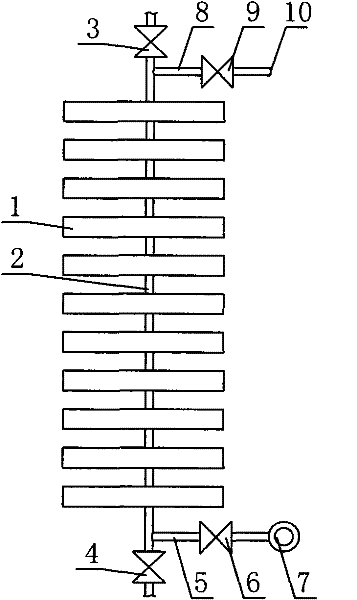
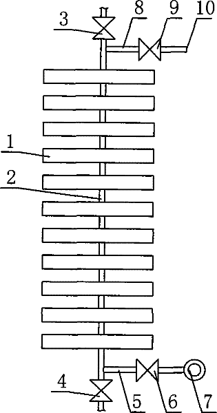
[0012] In specific implementation, such as figure 1 As shown, a blast furnace cooling structure includes several rectangular block-shaped staves 1, the staves 1 are made of cast iron, cooling water pipes 2 are arranged in the staves 1, the staves 1 are arranged in vertical rows and each vertical row The staves are penetrated by cooling water pipes 2 arranged vertically, wherein each vertical row of staves is divided into several groups, consisting of 11 staves 1, and the cooling water pipes 2 at the upper and lower ends of each group of staves 1 are provided with The upper on-off valve 3 and the lower on-off valve 4; on the cooling water pipeline 2 between the lower end of each group of staves 1 and the lower on-off valve 4, a lower bypass pipe 5 is horizontally connected, and a lower bypass pipe 5 is arranged in the lower bypass pipe...


PUM


Abstract

The invention discloses a blast furnace cooling structure, which comprises a plurality of cooling walls and cooling water pipelines, wherein the cooling walls are longitudinally arranged, and the cooling water pipelines are longitudinally penetrated in the cooling walls. The invention is characterized in that each row of cooling walls which are longitudinally arranged are divided into a pluralityof groups, and an upper switch valve and a lower switch valve are arranged on the cooling water pipelines at the upper end and the lower end of each group of cooling walls; the cooling water pipelinebetween the lower switch valve and the lower end of each group of cooling walls is also transversely provided with a lower by-pass pipe in a communication mode, a lower by-pass valve is arranged in the lower by-pass pipe, and a water pressure gauge is installed at the port of the other end of the lower by-pass pipe; and the cooling water pipeline between the upper switch valve and the upper end of each group of cooling walls is also transversely provided with an upper by-pass pipe in a communication mode, an upper by-pass valve is arranged in the upper by-pass pipe, and the port of the other end of the upper by-pass pipe is directly communicated with the atmosphere outside the blast furnace. The invention can reduce the influence of water leakage on blast furnace production, has the advantage of short leakage detecting time, and can accurately position the part of water leakage.

Description

technical field [0001] The invention relates to an ironmaking blast furnace, in particular to a blast furnace cooling structure. Background technique [0002] A blast furnace is an ironmaking shaft furnace with a circular cross section. Generally, steel plates are used as the furnace shell, and the shell is lined with refractory bricks. In order to meet the cooling requirements of the blast furnace during production, a cooling system is installed in the furnace wall of the blast furnace. The cooling system includes several rectangular cooling staves. The staves are made of cast iron. There are cooling water pipes in the staves. Arranged and each vertical row of staves is penetrated by a vertically arranged cooling water pipe. The cooling water enters from the lower end of the cooling water pipe and flows out from the upper end under the action of the water pump, thereby forming a cooling water cycle to cool the blast furnace. [0003] The blast furnace cooling system of th...

Claims


Application Information

Patent Timeline
Patent Type & Authority Patents(China)
IPC IPC(8): C21B7/10
Inventor 鲁德昌雷有高魏功亮王永贵陈永忠陈海全赵仕清
Owner CHONGQING IRON & STEEL (GRP) CO LTD
Learn More