Over-fire-air device for different load pulverized-coal fired boilers
A technology of overburning air and pulverized coal, applied in combustion equipment, lighting and heating equipment, etc., can solve the problems of uneven mixing, high content of overburning air, and reduced momentum of overburning air
- Summary
- Abstract
- Description
- Claims
- Application Information
AI Technical Summary
Problems solved by technology
Method used
Image
Examples
specific Embodiment approach 1
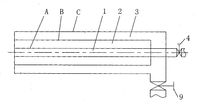
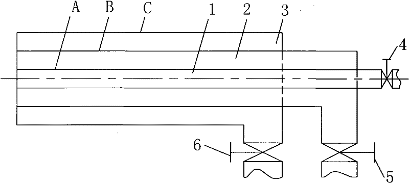
[0013] Specific implementation mode one: combine figure 1 Describe this embodiment. The overfire air device applicable to pulverized coal boilers with different loads described in this embodiment includes an inner air duct A, an intermediate air duct B, an outer air duct C, an inner air duct valve 4, and an intermediate air duct valve 5 and the outer air duct valve 6; the inner air duct A, the middle air duct B, and the outer air duct C are set sequentially from the inside to the outside and the three are coaxially arranged, and the inner cavity of the inner air duct A is an internal combustion exhaust air duct 1. The annular cavity between the outer surface of the inner air duct A and the inner wall surface of the intermediate air duct B is the intermediate overfired air duct 2. The space between the outer surface of the intermediate air duct B and the inner wall surface of the outer air duct C The annular cavity is the external burn-out air duct 3, the inner air duct valve 4...
specific Embodiment approach 2
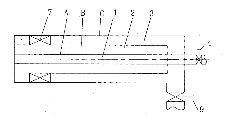
[0015] Specific implementation mode two: combination figure 2 To illustrate this embodiment, the over-burning air device in this embodiment further includes the swirl blades 7 of the outer air passage, and the swirling blades 7 of the outer air passage are arranged in the outer over-combustion air duct 3 . Both the internal overcombustion air duct 1 and the intermediate overcombustion air duct 2 of the present embodiment are used as direct-flow air ducts, and the external over-combustion air duct 3 is used as a swirl air duct, and the wind flowing out from the swirl air duct is swirl wind. The wind flowing out of the duct is direct current wind; the direct current wind has large axial momentum and strong penetrating power, and can mix and diffuse with the furnace flue gas at a distance from the burnout air nozzle; the axial momentum of the swirl wind is smaller than that of the direct current wind, Moreover, the swirling air has a tangential velocity, which can mix and diffus...
specific Embodiment approach 3
[0017] Specific implementation mode three: combination image 3To illustrate this embodiment, the over-fired air device in this embodiment further includes the swirl blades 8 in the middle air passage, and the swirl blades 8 in the middle air passage are arranged in the middle over-fired air passage 2 . The internal overcombustion air duct 1 of this embodiment is used as a straight air duct, and the middle overcombustion air duct 2 and the external overcombustion air duct 3 are all used as swirl air ducts; the wind flowing out from the swirl air duct is swirl wind, and The wind flowing out of the duct is direct current wind; the direct current wind has large axial momentum and strong penetrating power, and can mix and diffuse with the furnace flue gas at a distance from the burnout air nozzle; the axial momentum of the swirl wind is smaller than that of the direct current wind, Moreover, the swirling air has a tangential velocity, which can mix and diffuse with the furnace flu...
PUM
 Abstract
Description
Claims
Application Information
 - R&D
- Intellectual Property
- Life Sciences
- Materials
- Tech Scout
- Unparalleled Data Quality
- Higher Quality Content
- 60% Fewer Hallucinations
Browse by: Latest US Patents, China's latest patents, Technical Efficacy Thesaurus, Application Domain, Technology Topic, Popular Technical Reports.
© 2025 PatSnap. All rights reserved.Legal|Privacy policy|Modern Slavery Act Transparency Statement|Sitemap|About US| Contact US: help@patsnap.com


