Method for measuring alignment accuracy of machine vision system

A technology of machine vision system and alignment accuracy, which is applied in the direction of measuring devices, instruments, photoplate making process of patterned surface, etc. It can solve the problems that the accuracy measurement cannot reflect the situation of all CCD surfaces, and the accuracy measurement is mixed with other factors. Achieve the effect of reducing human interference and accurate precision

Inactive Publication Date: 2010-08-18
SHANGHAI MICRO ELECTRONICS EQUIP (GRP) CO LTD
View PDF5 Cites 14 Cited by
  • Summary
  • Abstract
  • Description
  • Claims
  • Application Information

AI Technical Summary

Problems solved by technology

[0006] Therefore, the traditional evaluation method faces the following challenges: the human subjectivity of accuracy measurement; the accuracy measurement is mixed with other factors; the accuracy measurement cannot reflect the situation of all CCD surfaces

Method used


Image

  • Method for measuring alignment accuracy of machine vision system
  • Method for measuring alignment accuracy of machine vision system
  • Method for measuring alignment accuracy of machine vision system

Examples


Embodiment Construction

[0026] Hereinafter, preferred embodiments according to the present invention will be described in detail with reference to the accompanying drawings. For convenience of description and highlighting of the present invention, relevant components existing in the prior art are omitted from the drawings, and the description of these well-known components will be omitted.

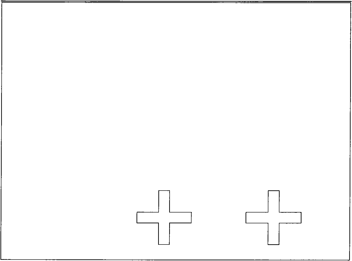
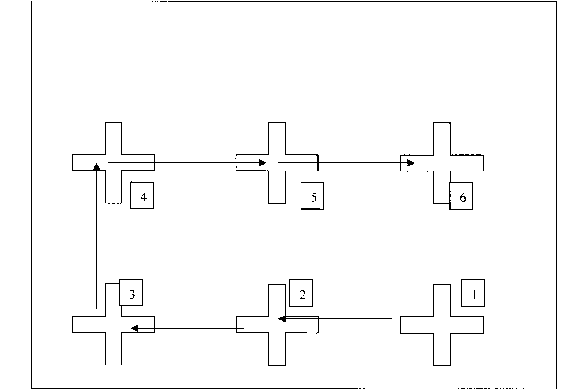
[0027] The present invention uses a marked substrate, see image 3 Schematic diagram of the labeled substrate shown. Several identical marks are evenly distributed on the marked substrate, and the positions and intervals of the marks are precisely measured and known; the stationary marked substrate is photographed by a machine vision system to obtain an image, and the image is subjected to graphic analysis ( The steps include but are not limited to: image segmentation, edge detection, centroid algorithm), and the pixel positions of each marker image in the field of view can be obtained. see Figure 4 The graph...


PUM


Abstract

The invention relates to a method for measuring the alignment accuracy of a machine vision system, comprising the following steps: providing a mark substrate on which a plurality of totally same marks with known positions and intervals are distributed; taking a picture of the mark substrate by using the machine vision system; segmenting the picture of the mark substrate; detecting the graph of each small picture of the mark substrate to obtain the edge of the graph, and calculating the center of the graph according to the characteristic of the graph; obtaining the position of the image of one mark in the machine vision system according to the positions of the small pictures in the whole picture; obtaining the physical positions of the marks on the mark substrate according to the transformation relation of existing coordinate systems of the machine vision system; and comparing the obtained physical positions of the marks with the positions of the known marks on the substrate to measure the alignment accuracy of the machine vision system.

Description

technical field [0001] The invention relates to a machine vision system, in particular to a method for measuring the alignment accuracy of the machine vision system in the field of photolithography. Background technique [0002] As an alignment sensor, the machine vision system is widely used in the field of lithography. The machine vision system is usually used to align the mark on the mask and the mark on the silicon wafer. After the multi-point alignment at both ends, the mask and the silicon wafer can be determined. Therefore, the circuit pattern on the mask can be accurately exposed to the silicon wafer; the accuracy of the machine vision system affects the positioning accuracy between the mask and the silicon wafer, and ultimately affects whether the circuit pattern can be exposed on the silicon wafer. correct location. [0003] Correctly evaluating the alignment accuracy of the machine vision system is of great significance for the index allocation and decomposition ...

Claims


Application Information

Patent Timeline
Patent Type & Authority Applications(China)
IPC IPC(8): G03F9/00G03F7/20G01B11/00
Inventor 王健
Owner SHANGHAI MICRO ELECTRONICS EQUIP (GRP) CO LTD
Why Eureka
Try Eureka