Current sampling circuit

A technology of current sampling and sampling resistors, which is applied to electrical components, adjusting electrical variables, and converting DC power input to DC power output. Effect of reducing power loss

Active Publication Date: 2010-08-18
BEIJING SUPLET +1
View PDF4 Cites 16 Cited by
  • Summary
  • Abstract
  • Description
  • Claims
  • Application Information

AI Technical Summary

Problems solved by technology

[0004] An embodiment of the present invention provides a current sampling circuit to solve the problems of large power loss and high cost of the current sampling circuit in the existing resonant zero-current switching circuit

Method used


Image

  • Current sampling circuit
  • Current sampling circuit
  • Current sampling circuit

Examples


Embodiment Construction

[0021] The following will clearly and completely describe the technical solutions in the embodiments of the present invention with reference to the accompanying drawings in the embodiments of the present invention. Obviously, the described embodiments are only some, not all, embodiments of the present invention. Based on the embodiments of the present invention, all other embodiments obtained by persons of ordinary skill in the art without making creative efforts belong to the protection scope of the present invention.

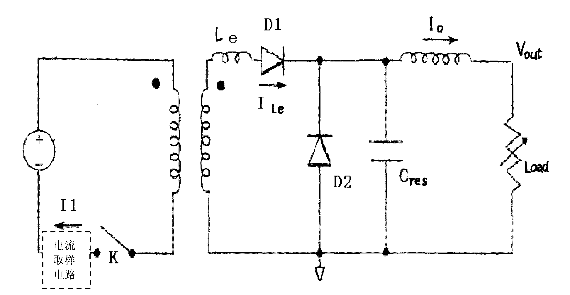
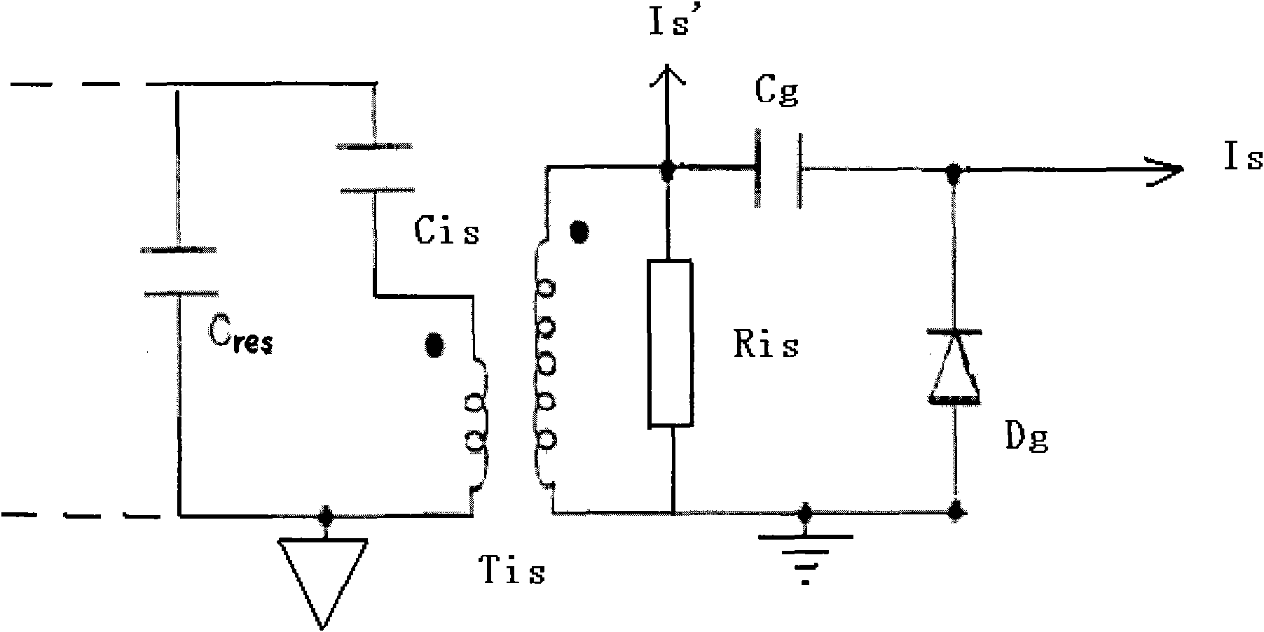
[0022] see figure 2 , an embodiment of the present invention provides a current sampling circuit, including a sampling branch connected in parallel with the oscillating capacitor Cres of the switching power supply circuit, a sampling resistor Ris, and a potential translation circuit connected in parallel with the sampling resistor Ris;

[0023] The sampling branch includes a shunt capacitor Cis and a current transformer Tis connected in series; the sampling r...


PUM


Abstract

The invention discloses a current sampling circuit and relates to the technical field of switching power supply by using a resonant zero current technology. The current sampling circuit comprises a sampling branch circuit, a sampling resistor and a potential translational circuit, wherein the sampling branch circuit is connected in parallel with an oscillating capacitor of a switching power supply circuit and the potential translational circuit is connected in parallel with the sampling resistor; the sampling branch circuit comprises a shut capacitor and a current transformer which are connected in series; the sampling resistor and the current transformer are connected in parallel; the potential translational circuit comprises a level isolating capacitor and a clamping diode, the cathode of the clamping diode and the level isolating capacitor are connected in series, and the anode of the clamping diode is grounded. Because the current sampling circuit is connected in parallel with a resonant capacitor, a current distribution relation is determined by a capacitance ratio of shunt capacitance to main circuit capacitance, and only very low current is available in the current sampling circuit, thereby the power loss of the current sampling circuit is greatly reduced. Furthermore, in the circuit, current detection of a heavy current circuit can be realized by using a small mutual inductor, thereby reducing the cost and the volume.

Description

technical field [0001] The invention relates to the technical field of a switching power supply using a resonance zero-current technology, in particular to a current sampling circuit. Background technique [0002] see figure 1 , is a typical forward resonant zero current (ZCS) circuit form in the switching power supply circuit in the prior art, and can also be simplified from forward to BUCK circuit form. Among them, the inductor Le and the capacitor Cres are the inductors and capacitors that generate oscillation; the value of Le is relatively small, so in practice, the leakage inductance of the transformer is generally used as Le; in order to ensure stable oscillation characteristics, a capacitor with high stability is used for Cres. In the prior art, the current sampling circuit is usually connected in series in the main circuit, namely figure 1 The position of the middle dotted line box is the usual position of the traditional current sampling circuit; the traditional c...

Claims


Application Information

Patent Timeline
Patent Type & Authority Applications(China)
IPC IPC(8): H02M3/24
Inventor 卢作烜周权
Owner BEIJING SUPLET
Why Eureka
Try Eureka