Adjustable multiband antenna

An adjustable, antenna technology, applied to antennas, resonant antennas, slot antennas, etc., can solve problems such as poor matching, difficult layout, low efficiency, etc., and achieve the effects of low production cost, good efficiency, and simple antenna structure

Active Publication Date: 2010-08-18
PULSE FINLAND
View PDF2 Cites 88 Cited by
  • Summary
  • Abstract
  • Description
  • Claims
  • Application Information

AI Technical Summary

Problems solved by technology

In addition, it is difficult to arrange such that the antenna match is good in both the lower and upper operating bands
Bad match also means inefficiency

Method used


Image

  • Adjustable multiband antenna
  • Adjustable multiband antenna
  • Adjustable multiband antenna

Examples


Embodiment Construction

[0020] Figure 1 has been described in connection with the description of the prior art.

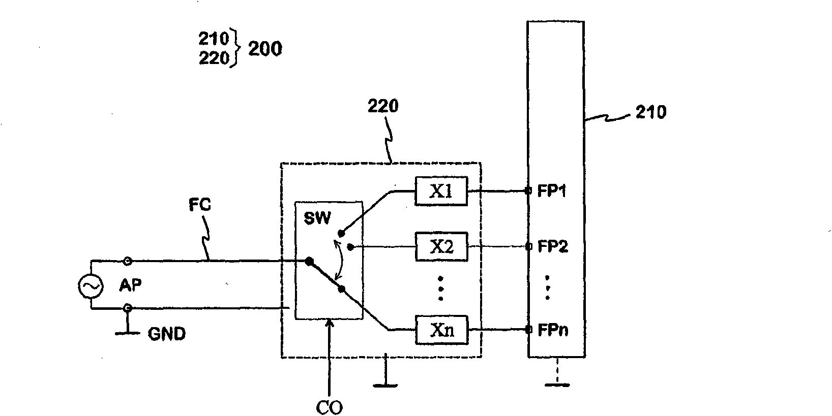
[0021] Fig. 2 shows as a block diagram the principle of the antenna according to the invention. The antenna 200 includes a radiating element 210 and a conditioning circuit 220 . Instead of the normal one feed point, there are several feed points FP1, FP2, --, FPn in the radiating element. The symbol 'n' means the number of feed points that can be selected. The radiating element 210 is realized such that the antenna has at least two separate operating frequency bands, a lower frequency band and an upper frequency band. The adjustment circuit 220 includes a multi-way switch SW and reactive circuits X1, X2, -, Xn. The number of multiplex terminals or outputs of the switch SW is the same as the number of feeding points in the radiating element. Each feed point is connected to a different output of the switch through a reactive circuit. The common terminal or input of the switch SW is con...


PUM


Abstract

An adjustable multi-band planar antenna especially applicable in mobile terminals. The feed of the antenna can be connected by a multiple-way switch (SW) to at least two alternative points (FP1, FP2, FP3) in the radiator (310). When the feed point is changed, the resonance frequencies and thus the operating bands of the antenna change. Besides the basic dimensions of the antenna, the distance (x, y, z) of each feed point to other feed points and possible short-circuit point in the radiator, the value of the series capacitance (C31; C32; C33) belonging to a reactive circuit between the feed point and switch and the distance of the ground plane (GND) from the radiator are variables in the antenna design.

Description

technical field [0001] The present invention relates to an adjustable multi-band antenna notably intended for mobile terminals. Background technique [0002] Adjustability of the antenna means in this specification that the resonant frequency of the antenna can be changed electrically. The aim is that the operating band of the antenna around the resonant frequency always covers the frequency range assumed by the function each time. There are different reasons for the need for adjustability. Portable radio devices like mobile terminals have become smaller in every respect (also in thickness). In this case, the distance between the radiation plane and the ground plane inevitably becomes shorter with respect to, for example, a planar antenna which is a very common antenna type in mobile terminals. This results in that eg the bandwidth of the antenna will be reduced. In addition, the reduction in device size means that its ground plane is also smaller. This leads to a reduc...

Claims


Application Information

Patent Timeline
Patent Type & Authority Applications(China)
IPC IPC(8): H01Q1/24H01Q1/38H01Q9/04H01Q5/02H01Q5/15
CPCH01Q9/145H01Q13/10H01Q1/243H01Q1/38H01Q9/42H01Q9/04H01Q5/00
Inventor Z·米洛萨夫杰维奇
Owner PULSE FINLAND
Why Eureka
Try Eureka