Protective door structure of knitting mechanism of computer flat knitting machine

A technology for flat knitting machines and protective doors, which is applied in knitting, weft knitting, textiles and papermaking, etc. It can solve the problems of poor integrity, affecting the viewing effect, and poor sealing performance, and achieves good sealing effect, convenient and fast opening and closing. overall ideal effect

Inactive Publication Date: 2012-05-02
常熟市碧溪新区和宝纺织机械厂
View PDF10 Cites 3 Cited by
  • Summary
  • Abstract
  • Description
  • Claims
  • Application Information

AI Technical Summary

Problems solved by technology

Although this structure can meet the requirements of use, that is, it plays a role in shielding the braiding mechanism, but it has the following shortcomings in actual use: First, the opening degree is limited, which affects the working space during maintenance and overhaul, because if the middle If the door body 1 moves to both sides, then both sides are in a closed state; on the contrary, if the door body 1 on both sides is moved to the middle, then the middle area is in a closed state, that is to say, a part of the working space is blocked by the door body 1, It affects the efficiency of maintenance and repair; the second is poor sealing, because the door body 1 is a sliding door structure. In the closed state, there are gaps between the door bodies 1 in different tracks, and external dust will invade the weaving mechanism from the gap; three. It is poor integrity, which affects the opening and closing efficiency, because whether it is to open or close the door, it is necessary to operate the door body 1 one by one, and it also affects the overall viewing effect

Method used


Image

  • Protective door structure of knitting mechanism of computer flat knitting machine
  • Protective door structure of knitting mechanism of computer flat knitting machine
  • Protective door structure of knitting mechanism of computer flat knitting machine

Examples


Embodiment Construction

[0016] In order to enable the examiners of the patent office, especially the public, to understand the technical essence and beneficial effects of the present invention more clearly, the applicant will describe in detail below in conjunction with the accompanying drawings in the form of embodiments, but none of the descriptions of the embodiments is a description of the present invention. Restriction of the inventive solution, any equivalent transformation made according to the concept of the present invention which is only in form but not in substance shall be regarded as the scope of the technical solution of the present invention.

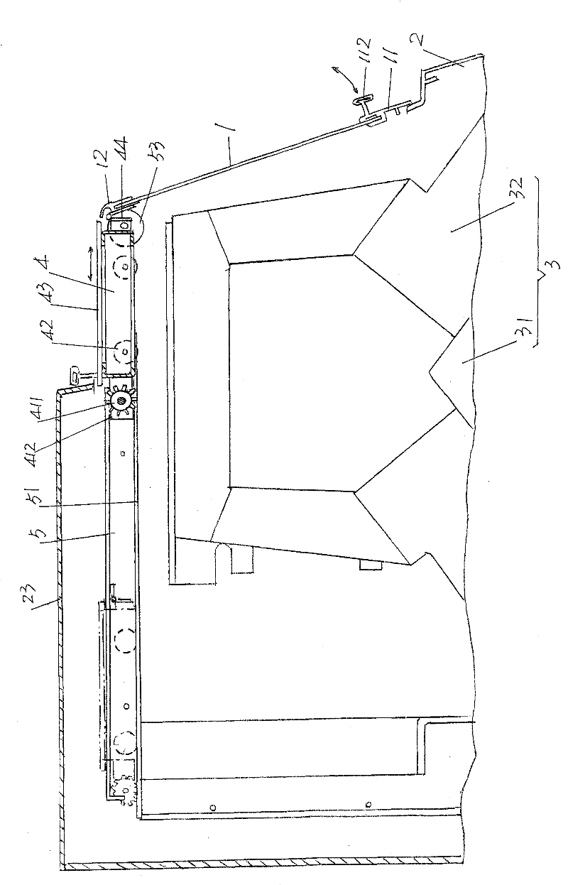
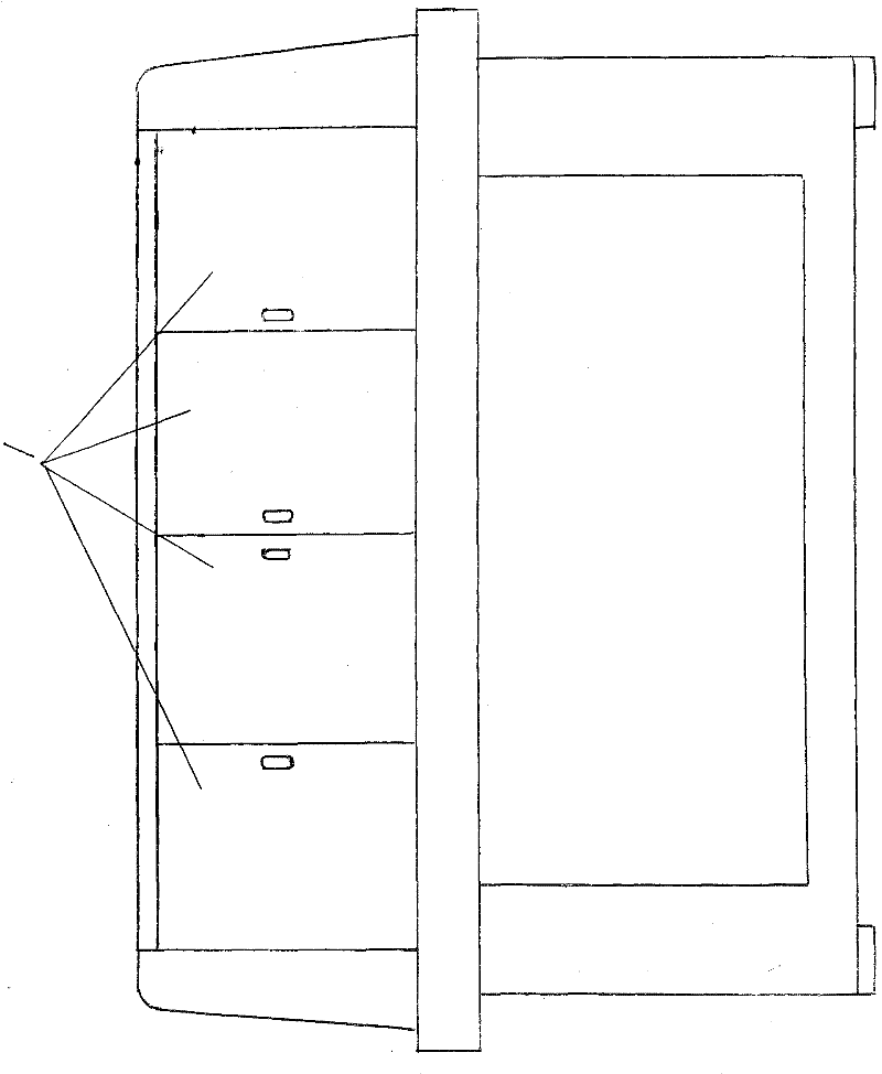
[0017] please see figure 1 and figure 2 ,exist figure 1 Provided in the computer knitting flat knitting machine is used to set the knitting mechanism 3 ( figure 2 Shown) a machine base 2, a left bedside cover 21 is fixed on the upper surface of one end of the length direction of the machine base 2, that is, the upper surface of the left en...


PUM


Abstract

The invention relates to a protective door structure of a knitting mechanism of a computer flat knitting machine, which belongs to knitting machinery. The computer flat knitting machine comprises a machine seat, wherein a left bed head sheath is configured at one end of the machine seat, and a right bed head sheath is configured at the other end; the knitting mechanism is positioned between the left bed head sheath and the right bed head sheath; and top protecting plates are configured on the left bed head sheath and the right bed head sheath. The protective door structure comprises a door body, a linking frame and a pair of guide rails, wherein a door body lower frame strip is fixed to the lower edge of the length direction of the door body, and a door body upper frame strip is fixed to the upper edge; one side of the length direction of the linking frame is articulated with the door body upper frame strip, and the other side is provided with a gear shaft; both ends of the gear shaftare provided with gears; both ends of the width direction of the linking frame are provided with linking frame idler wheels; and the guide rail bottom walls of all the guide rails are provided with gear holes, the linking frame idler wheels and the guide rails form a rolling pair, and the gears are meshed with the gear holes. The invention can be completely opened and closed and provide enough operating space for the clean maintenance of examination and maintenance staffs, and has good seal effect, ideal integrity and convenient and rapid opening and closing.

Description

technical field [0001] The invention belongs to the technical field of knitting machines, and in particular relates to a protective door structure of a knitting mechanism of a computerized flat knitting machine. Background technique [0002] As is well known in the industry, in order to protect the knitting mechanism of the computerized flat knitting machine, such as the machine head, the needle bed and the knitting needles, to avoid the invasion of dust and foreign matter in the workplace, and also to play a role in safety protection, usually in the computer One side of the length direction of the flat knitting machine, that is, the side facing outwards under the working state, is equipped with a protective door, and most of the protective doors are transparent, so that the staff can check the working status of the knitting mechanism through the protective door. When it is necessary to replace the damaged knitting needles on the needle bed (also known as the needle plate), ...

Claims


Application Information

Patent Timeline
Patent Type & Authority Patents(China)
IPC IPC(8): D04B15/00
Inventor 邵锡良
Owner 常熟市碧溪新区和宝纺织机械厂
Why Eureka
Try Eureka