Device and method for detecting pavement evenness based on image moire method

A detection device and flatness technology are applied in the field of road surface flatness detection methods, which can solve the problems of low test accuracy, low detection accuracy, slow test speed, etc., and achieve good interference fringe contrast, high measurement efficiency, and easy implementation. Effect

Inactive Publication Date: 2010-08-25
EAST CHINA JIAOTONG UNIVERSITY
View PDF6 Cites 17 Cited by
  • Summary
  • Abstract
  • Description
  • Claims
  • Application Information

AI Technical Summary

Problems solved by technology

[0003] In the 1970s and 1980s, domestic road surface roughness measurement equipment mainly included spirit levels, 3m rulers, etc., with low test accuracy, slow speed, and low efficiency, and relied on manual operation
By the early 1990s, the detection methods had improved to a certain extent, such as the continuous flatness meter, but there were still shortcomings of poor repeatability and slow test speed
At present, the road surface roughness testing equipment adopted in China mainly includes contact mechanical d

Method used


Image

  • Device and method for detecting pavement evenness based on image moire method
  • Device and method for detecting pavement evenness based on image moire method
  • Device and method for detecting pavement evenness based on image moire method

Examples


Embodiment 1

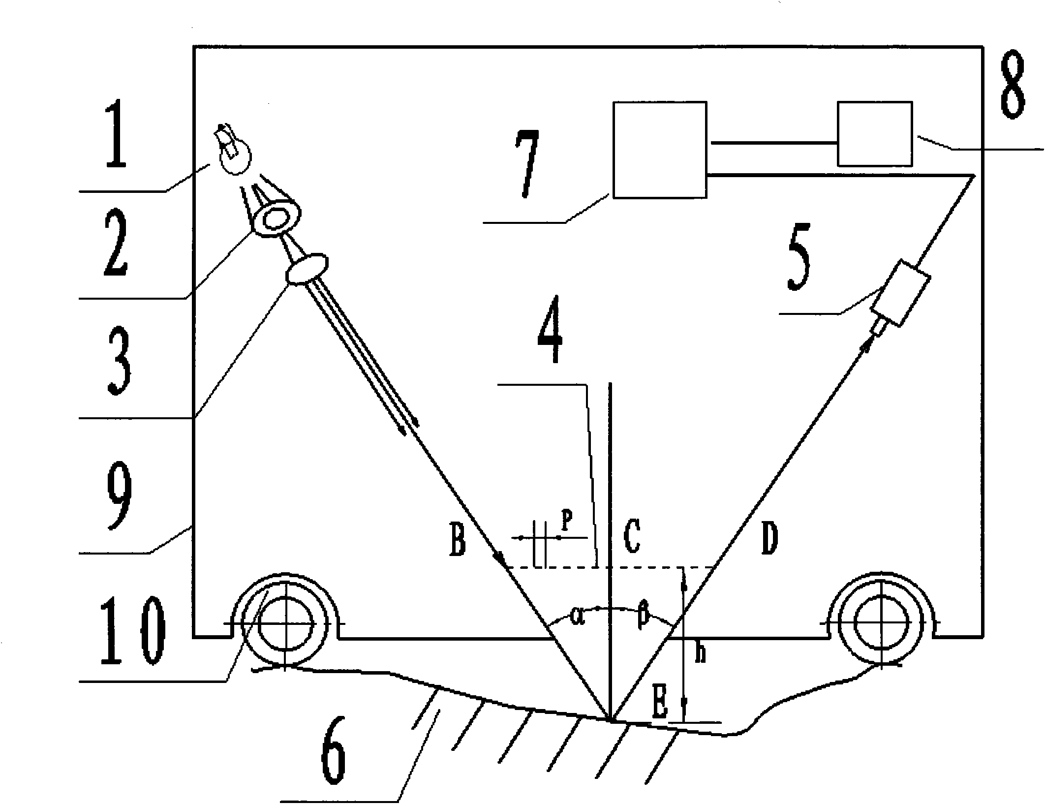
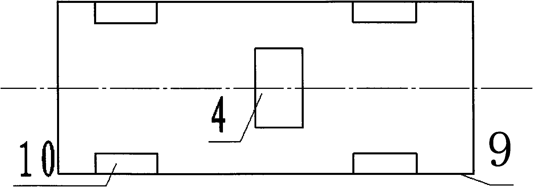
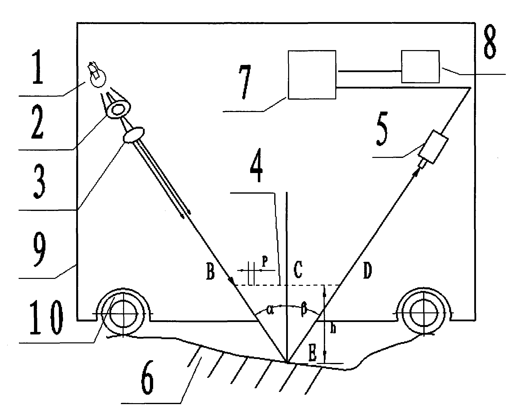
[0020] Embodiment 1, a road surface roughness detection device based on the image moiré method, wherein: it consists of a car body 9, a wheel 10, a reference grid 4 arranged on the inner floor of the vehicle, a light source 1 located on one side of the reference grid 4, a filter device 2, focusing lens 3, CCD camera 5 on the other side, road surface 6 below the reference grid 4, terminal processing device 7 and printout device 8; light source 1, filter 2, and focusing lens 3 are linear Arranged, the light strip emitted by the light source 1 can cover the longitudinal road surface 6, the light emitted by the light source 1 forms an angle α with the normal line of the reference grid 4, and the incident light entering the CCD camera 5 forms an angle β with the grating 4; the CCD camera 5 can obtain the road surface 6 moiré image information; the terminal processing device 7 is connected with the CCD camera 5.

Embodiment 2

[0021] Embodiment 2, the detailed implementation steps of the road surface roughness detection method based on the image moiré method are as follows:

[0022] Firstly, the car body 9 is pulled forward by the tractor, and the light strips emitted by the laser light source 1 pass through the spatial filter 2 to form a light field with a large area, and then become parallel light after passing through the focusing lens 3, and pass through the reference grating 4 The formed image is projected onto the road surface 6, and the image and the reference grid 4 interfere with each other to form an interference moiré image. The CCD camera 5 captures and saves the interference moiré image and transmits it to the terminal processing device 7, and can perform real-time dynamic adjustment with reference to the image aggregation effect on the screen of the terminal processing device 7.

[0023] Secondly, the moiré image is filtered by the image processing software in the terminal processing d...

Embodiment 3

[0044]Embodiment 3, a road surface roughness detection device based on the image moiré method, comprising a light source 1, a filter 2, a focusing lens 3, a reference grid 4, a CCD camera 5, a terminal processing device 7, a car body 9 and wheels 10; wherein: The bottom plate in the vehicle body 9 is provided with a reference grid 4, the light source 1, the filter 2, and the focusing lens 3 are all located on one side of the reference grid 4, the CCD camera 5 is located on the other side of the reference grid 4, and the road surface 6 is located on the side of the reference grid 4. Below, the vehicle body 9 and the wheels 10 are connected and arranged on the road surface 6 ; the terminal processing device 7 is connected with the CCD camera 5 .


PUM


Abstract

The invention relates to a device and method for detecting the pavement evenness based on an image moire method. The device comprises a car body, wheels, a reference grid arranged on a bottom plate in the car, a light source, a filter and a focusing lens and a CCD camera, wherein the light source, the filter and the focusing lens are arranged at one side of the reference grid and the CCD camera is arranged at the other side of the reference grid. The device also comprises a notebook computer and a printing device. The computer is connected with the CCD camera and is provided with image processing software which can store and process the pavement images in real time. The invention introduces the image moire method into pavement detection, realizes automation and full digitalization of detection and has the advantages of simple operation, easy realization, low cost, high precision, etc.

Description

Technical field: [0001] The invention relates to a detection method of road surface roughness, in particular to a road surface smoothness detection device and detection method based on image moiré method. Background technique: [0002] At present, the mileage of expressways in my country is increasing rapidly. Road surface roughness is an important indicator of ride comfort and safety, and also an important indicator of road performance, so it is the direct basis for road users to judge whether a road is good or bad. How to obtain the smoothness of the road surface faster, better and more accurately has become a problem of great concern to the highway traffic departments at all levels. [0003] In the 1970s and 1980s, domestic road surface roughness measurement equipment mainly included spirit levels, 3m rulers, etc., with low test accuracy, slow speed, and low efficiency, and relied on manual operation. By the early 1990s, the detection methods had improved to a certain e...

Claims


Application Information

Patent Timeline
IPC IPC(8): E01C23/01G01B11/30
Inventor 欧阳爱国罗茶根刘燕德孙旭东刘伟
Owner EAST CHINA JIAOTONG UNIVERSITY
Why Eureka
Try Eureka