
Vortex fluid machinery

A fluid machinery and scroll technology, which is applied to rotary piston machinery, mechanical equipment, liquid fuel engines, etc., can solve the problems of no disclosure of capacity control and simultaneous back pressure control, no description of back pressure control, etc. Simple structure, secure sealing, and the effect of suppressing sliding friction loss

Active Publication Date: 2010-08-25
HITACHI JOHNSON CONTROLS AIR CONDITIONING INC
View PDF1 Cites 10 Cited by
  • Summary
  • Abstract
  • Description
  • Claims
  • Application Information

AI Technical Summary

Problems solved by technology

[0012] The conventional scroll fluid machine disclosed in Patent Document 2 has the following problems: there is no description related to back pressure control, and there is no disclosure of a method for simultaneously performing capacity control and back pressure control.

Method used


Image

  • Vortex fluid machinery
  • Vortex fluid machinery
  • Vortex fluid machinery

Examples


no. 1 approach

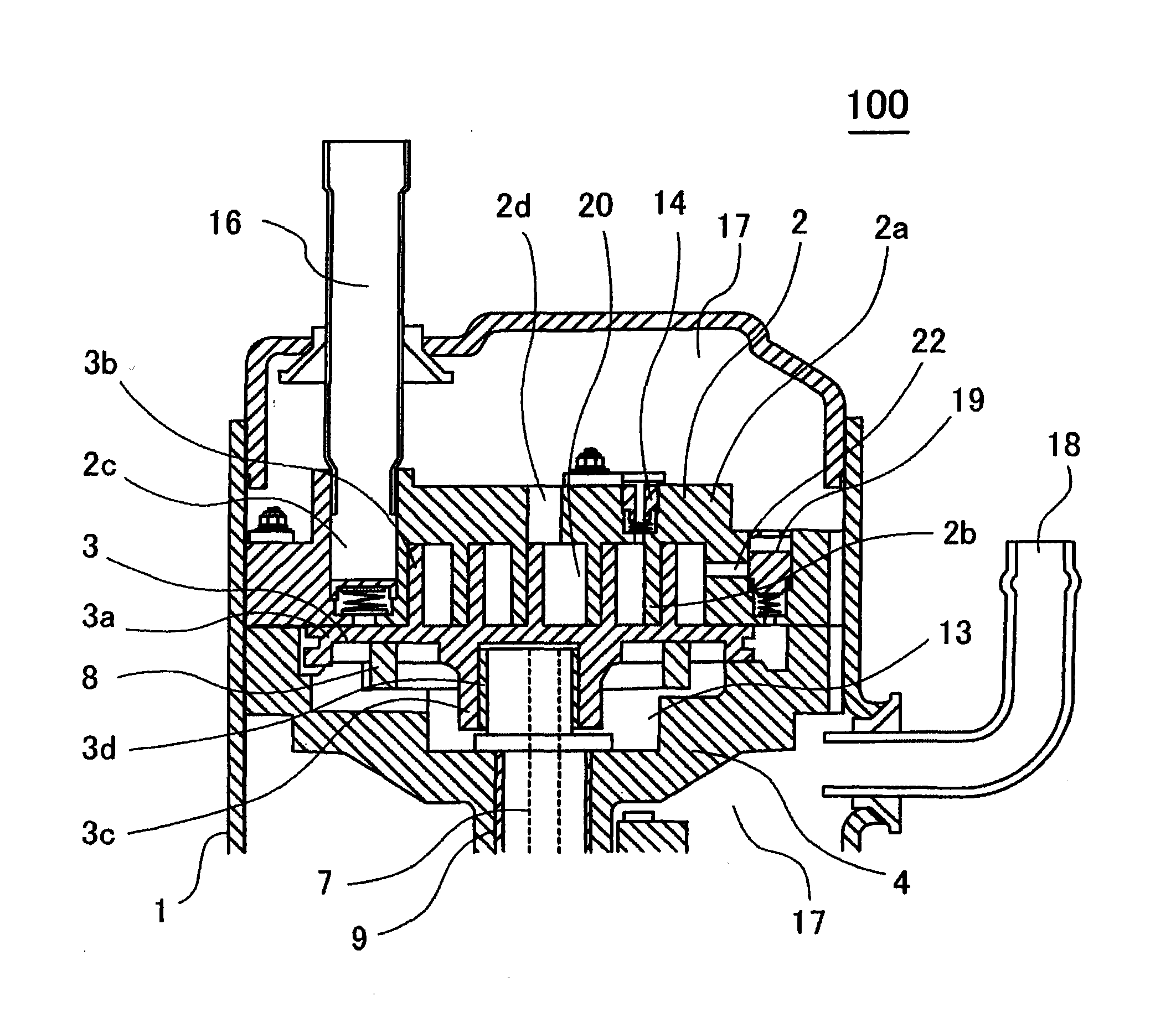
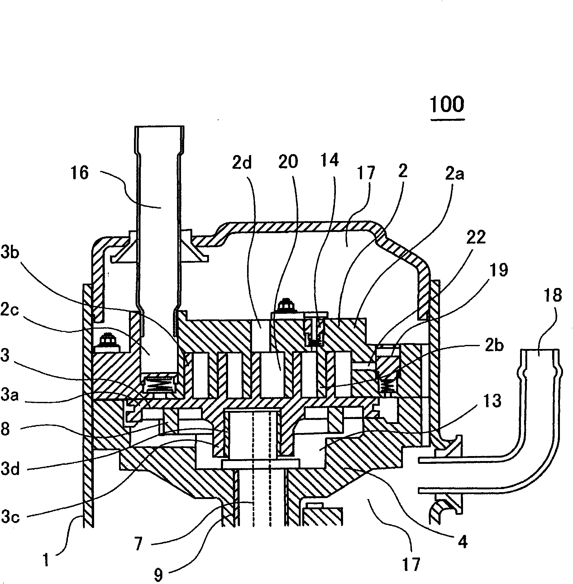
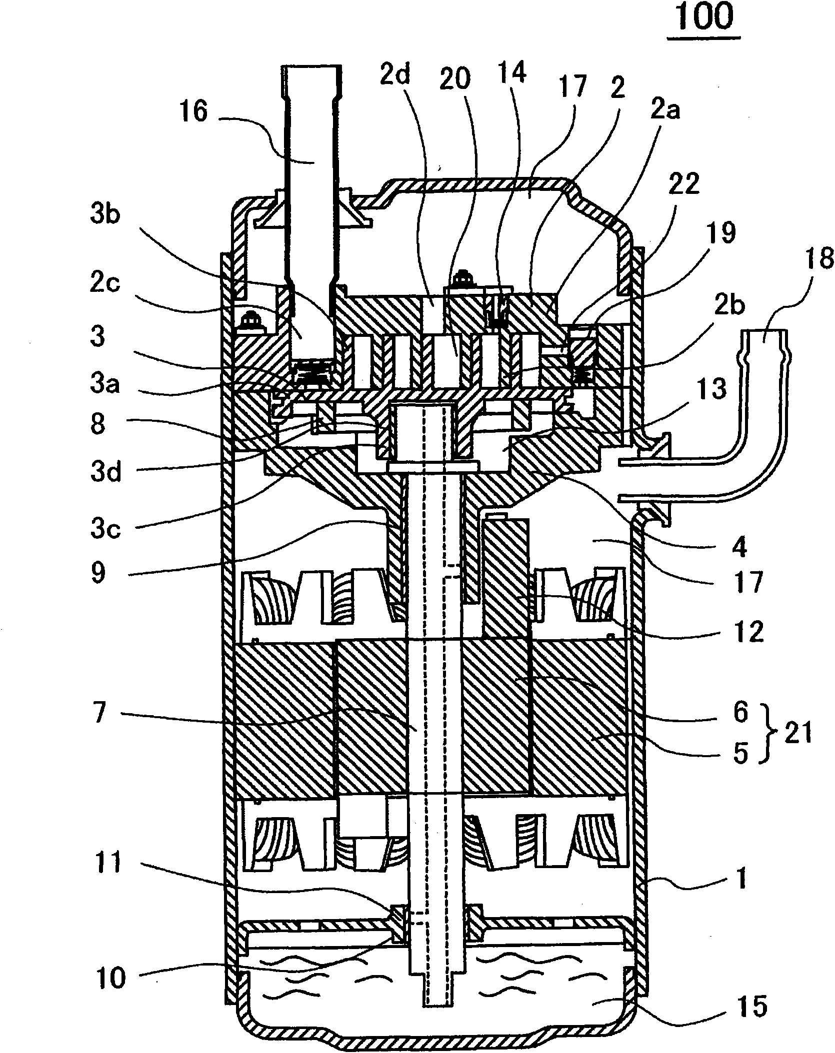
[0079] A scroll compressor 100 according to a first embodiment of the present invention will be described with reference to FIGS. 1 to 4 . First, the scroll compressor 100 will be described with reference to FIGS. 1 and 2 . Fig. 1 is a sectional view of a compression mechanism of a scroll compressor according to a first embodiment of the present invention. Fig. 2 is a sectional view of the entire scroll compressor.

[0080] The scroll compressor 100 has a structure in which a compression mechanism performing a compression operation and a drive mechanism including an electric motor are housed in a closed casing 1 .

[0081] The compression mechanism includes the following basic elements: a non-revolving scroll 2 , a revolving scroll 3 , and a frame 4 . Compression chamber 20 is formed by meshing non-orbiting scroll 2 and orbiting scroll 3 .

[0082] The non-orbiting scroll 2 includes the following basic components: an end plate 2a; and a scroll-shaped wrap 2b erected on the ...

no. 2 approach

[0105] A second embodiment of the present invention will be described using FIGS. 5 and 6 . 5 and 6 are structures in which the capacity control mechanism and the back pressure control mechanism are separated. In FIGS. 5 and 6 , although the back pressure control mechanism is not shown, the back pressure control mechanism having the function of adjusting the back pressure as described in the first embodiment is provided. Alternatively, a back pressure control mechanism is provided in which the needle valve 19c of the back pressure control mechanism 19 is fixed by pressing etc., the spring length of the back pressure control spring 19b is made constant, and the full operation without capacity control is provided. Under the condition that the sealing performance of the compression chamber 20 is sufficiently ensured, it is set as (back pressure)=(suction pressure)+(constant value). Alternatively, a back pressure control mechanism that does not use the valve described in the firs...


PUM


Abstract

A Vortex fluid machinery is provided which can automatically control the capability based on the operational conditions without any complicated branch piping, as a result, the manufacturing cost is reduce by a wide margin while a capacity control and a back pressure control with superior responsivity are obtained. In said vortex fluid machinery, back pressure is applied at least from the opposed side of the work chamber of one side of the rotary vortex disc or non rotary vortex disc to the work chamber side. There also provided a capability control mechanism which can control the back pressure based on running condition.

Description

technical field [0001] The present invention relates to a scroll fluid machine, for example, a scroll compressor, a scroll vacuum pump, a scroll blower, and the like suitable for handling compressive gas or liquid such as refrigerant in a working fluid. Background technique [0002] As a conventional scroll fluid machine, Unexamined-Japanese-Patent No. 2000-314382 (patent document 1) is disclosed. [0003] This scroll fluid machine has: a working chamber, which is formed by engaging a revolving scroll and a non-revolving scroll vertically provided with spiral wraps on respective bottom plates (end plates); and a motor, which consists of a stator and a rotor. Composition; shaft, which passes through the rotor and transmits the rotational force of the rotor. The orbiting scroll is prevented from rotating by an anti-rotation mechanism, and at the same time performs orbital motion relative to the non-orbiting scroll. The working fluid flowing into the working chamber from the ...

Claims


Application Information

Patent Timeline
IPC IPC(8): F04C18/02F04C28/18F04C2/18F04C14/18
CPCF04C18/0215F04C18/0269F04C23/008F04C28/18F04C28/26F04C29/124F04C2210/26F04C2240/40Y10S415/00Y10S417/902
Inventor 藤村和幸坪野勇香曾我部弘胜岛田敦田所哲也大沼敦村上晃启新村修平
Owner HITACHI JOHNSON CONTROLS AIR CONDITIONING INC
Learn More