Supercharge Your Innovation With Domain-Expert AI Agents!

Fan with improved rotational speed control module and fan group constituted thereby

A speed control, improved technology, applied in pump control, excitation or armature current control, non-varactor pump, etc., can solve the problems of running status feedback, improve other fans, cannot reduce manufacturing costs, etc., to achieve a simple circuit structure, the effect of reducing the manufacturing cost

Active Publication Date: 2010-08-25
SUNONWEALTH ELECTRIC MACHINE IND
View PDF1 Cites 0 Cited by
  • Summary
  • Abstract
  • Description
  • Claims
  • Application Information

AI Technical Summary

Problems solved by technology

[0005] However, since the two DC fans in the above-mentioned multi-motor fan system do not feed back their running status to the existing speed control module, the switch circuit constituting the speed control module cannot control the speed of the two DC fans according to the running status of the two DC fans. adjustment
In other words, the speed of each DC fan in the multi-motor fan system cannot be changed automatically, so that the multi-motor fan system cannot correspondingly increase the speed of other fans when the operation state of any DC fan is abnormal. The existing fan speed control device Obviously there is a shortcoming of being unable to respond immediately to the status of each DC fan
In addition, this existing fan speed control device still needs to carry out circuit design according to the number of fans in the multi-fan system, which obviously cannot reduce the manufacturing cost

Method used


Image

  • Fan with improved rotational speed control module and fan group constituted thereby
  • Fan with improved rotational speed control module and fan group constituted thereby
  • Fan with improved rotational speed control module and fan group constituted thereby

Examples


no. 1 example

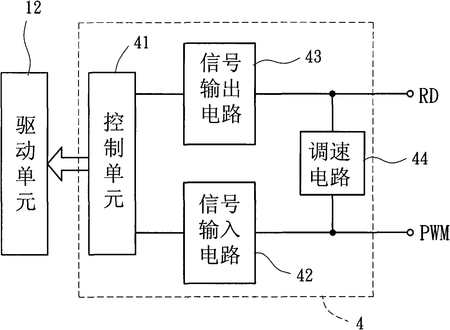
[0042] Please refer to FIG. 6, which shows the circuit layout of the speed control module 4' according to the second embodiment of the present invention, and the speed control modules of each fan when the fans with the speed control module 4' are used to form the fan group. 4' electrical connections. Compared with the aforementioned first embodiment of the present invention, the speed regulating circuit 44' provided in the speed control module 4' of this embodiment also has a first terminal 441' and a second terminal 442', and the first The terminal 441' and the second terminal 442' are also respectively connected to the output terminal 432 and the signal input terminal 411; however, the speed regulating circuit 44' includes a diode 444 as the electronic switch, and the cathode of the diode 444 is connected to the The first terminal 441', and the anode of the diode 444 is connected to the second terminal 442'. In addition, when several fans form the fan group, the output term...


PUM


Abstract

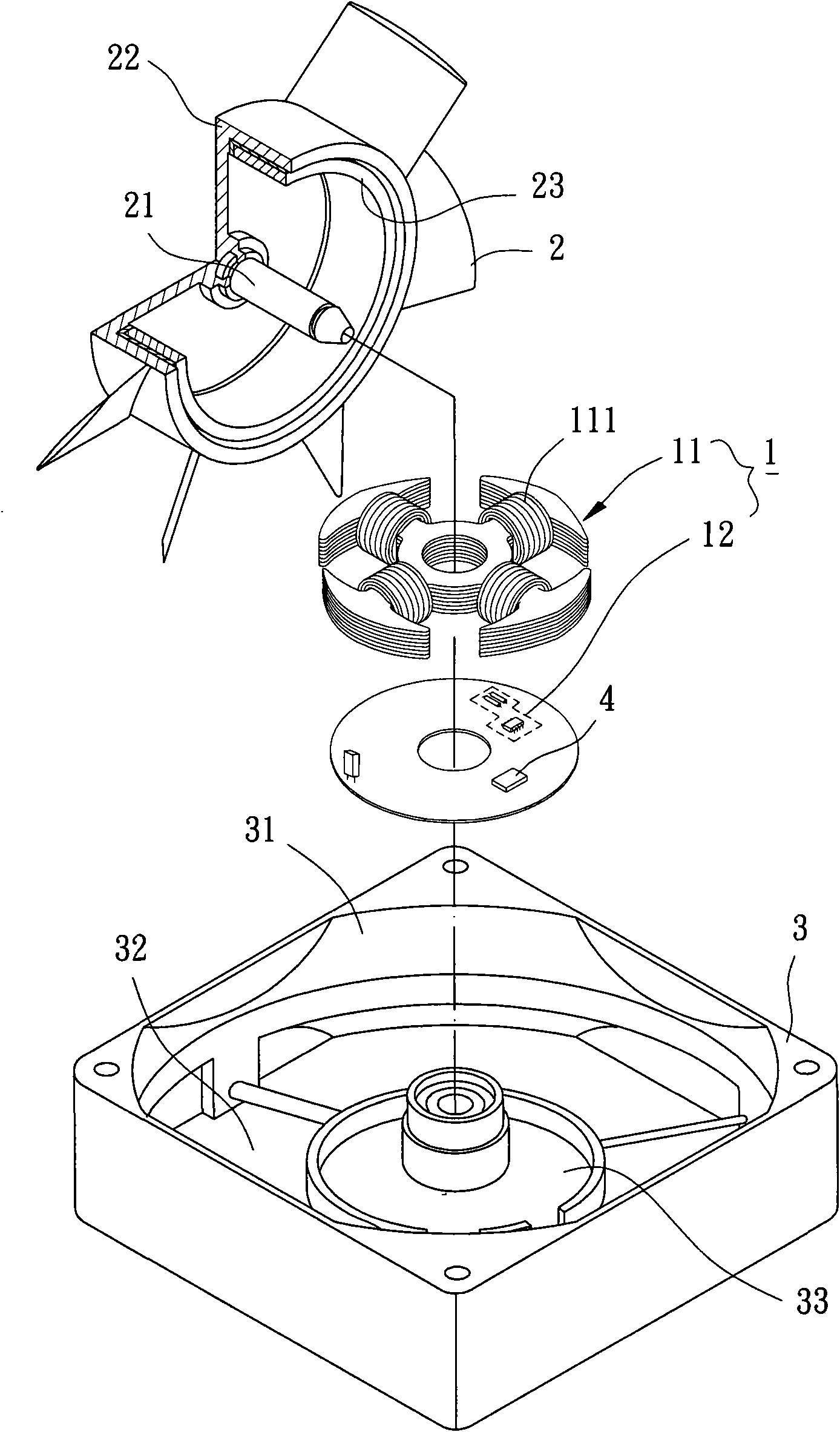
The invention relates to a fan with an improved rotational speed control module, which comprises a stator, a rotor and the rotational speed control module, wherein the stator comprises a driving unit, and the driving unit produces current for leading the stator to produce an alternating magnetic field, thereby driving the rotor to rotate relative to the stator. The rotational speed control module comprises a control unit and a speed regulation circuit, wherein the control unit produces a control command and sends to the driving unit, and the control unit additionally outputs a state signal for controlling the speed regulation circuit to decide whether inputting a pulse width modulation signal needs into the control unit or not.

Description

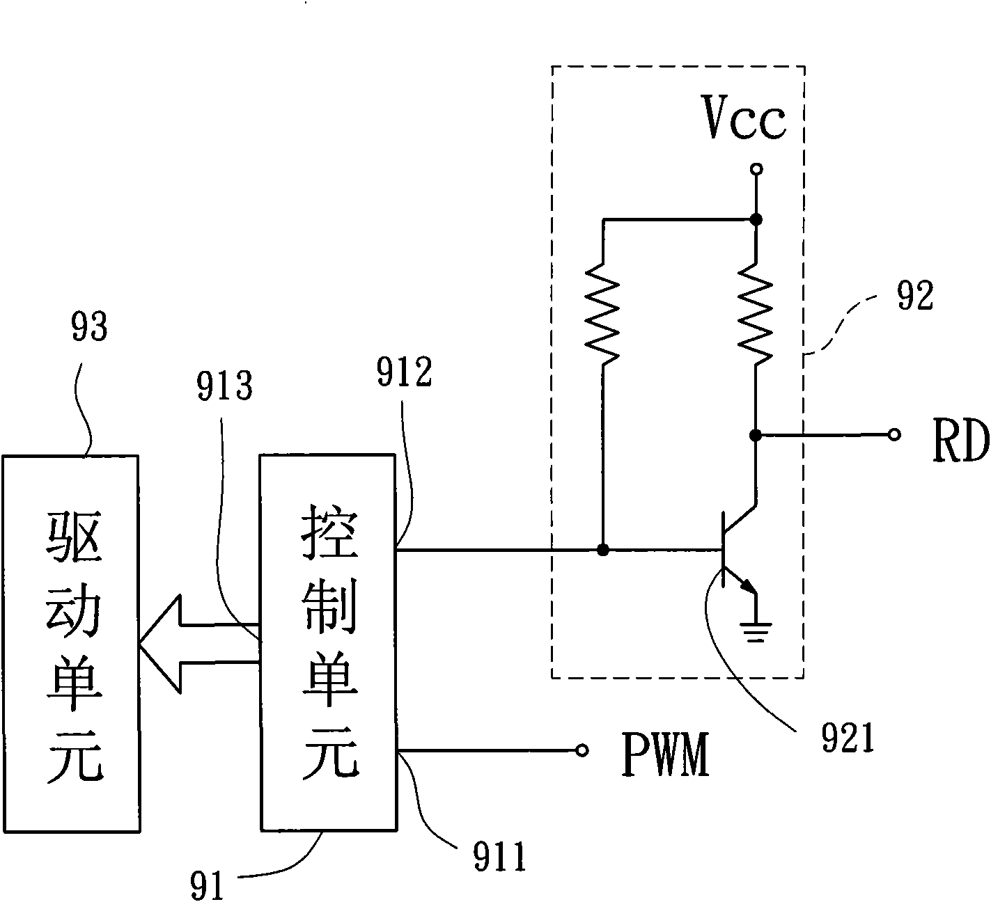
technical field [0001] The invention relates to a fan with an improved rotation speed control module, in particular to a fan with an improved rotation speed control module for forming a fan group. Background technique [0002] Please refer to FIG. 1 , which shows a conventional speed control module, which includes a control unit 91 and a signal output circuit 92 . The control unit 91 has a signal input terminal 911, a signal output terminal 912 and a control command output terminal 913. The signal input terminal 911 is used to connect to a pulse width modulation signal terminal PWM, and the signal output terminal 912 is connected to and outputs a state Signal to the signal output circuit 92, and the control command output terminal 913 is connected and output a control command to the drive unit 93 of a fan; the signal output circuit 92 has a transistor 921 as an electronic switch, so that the signal output circuit 92 outputs a digital signal according to the status signal. ...

Claims


Application Information

Patent Timeline
Patent Type & Authority Applications(China)
IPC IPC(8): F04D19/00F04D27/00H02P7/28
Inventor 洪银树黄俊源郑宗根
Owner SUNONWEALTH ELECTRIC MACHINE IND
Features
  • R&D
  • Intellectual Property
  • Life Sciences
  • Materials
  • Tech Scout
  • Unparalleled Data Quality
  • Higher Quality Content
  • 60% Fewer Hallucinations
Learn More