Distribution photometer system

A goniophotometer and optical signal technology, which is applied in the field of optical testing, can solve problems such as the influence of angle control accuracy and photometric measurement accuracy, low reliability and real-time performance, and complex management and maintenance, so as to reduce mutual interference and ensure Safe and less interference between modules

Active Publication Date: 2010-08-25
远方谱色科技有限公司
View PDF0 Cites 3 Cited by
  • Summary
  • Abstract
  • Description
  • Claims
  • Application Information

AI Technical Summary

Problems solved by technology

[0008] The present invention mainly solves the problem that a large number of long wires are directly connected to the control center of the existing goniophotometer system, which easily causes signal loss and interference on the wires, resulting in low reliability and real-time performance of the entire goniophotometer system and poor angle control accuracy. And photometric measurement accuracy is affected and the management and maintenance of the system are more complicated technical problems, and solve the technical problems of wire connection in the distribution photometer to avoid winding and strain during rotation; provide a high transmission performance that makes full use of the digital signal channel And strong anti-interference ability, effectively improve system reliability and real-time performance, ensure photometric measurement accuracy and angle control accuracy of the goniophotometer system
[0009] The invention also solves the problem that the existing goniophotometer system has long and many wires and is prone to entanglement, so that the rotating parts need to take limiting measures, which affects the measurement and sampling, and long-term operation is likely to cause strain on the wires and even bring safety. Hidden technical problems; provide a goniophotometer system that reduces the number of connecting wires, improves the wiring of the wires, makes the wires less prone to entanglement, thus does not affect the measurement and sampling, reduces damage to the wires, prolongs the service life of the wires, and ensures safety

Method used


Image

  • Distribution photometer system
  • Distribution photometer system
  • Distribution photometer system

Examples


Embodiment 1

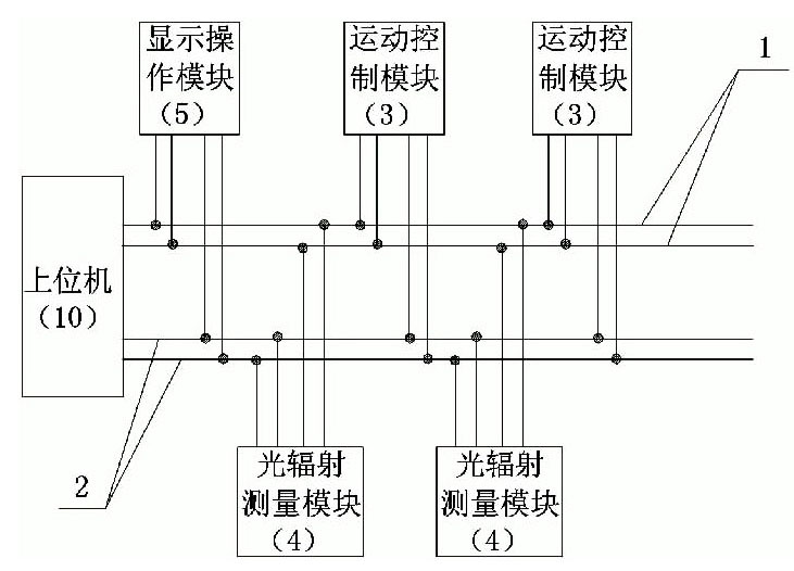
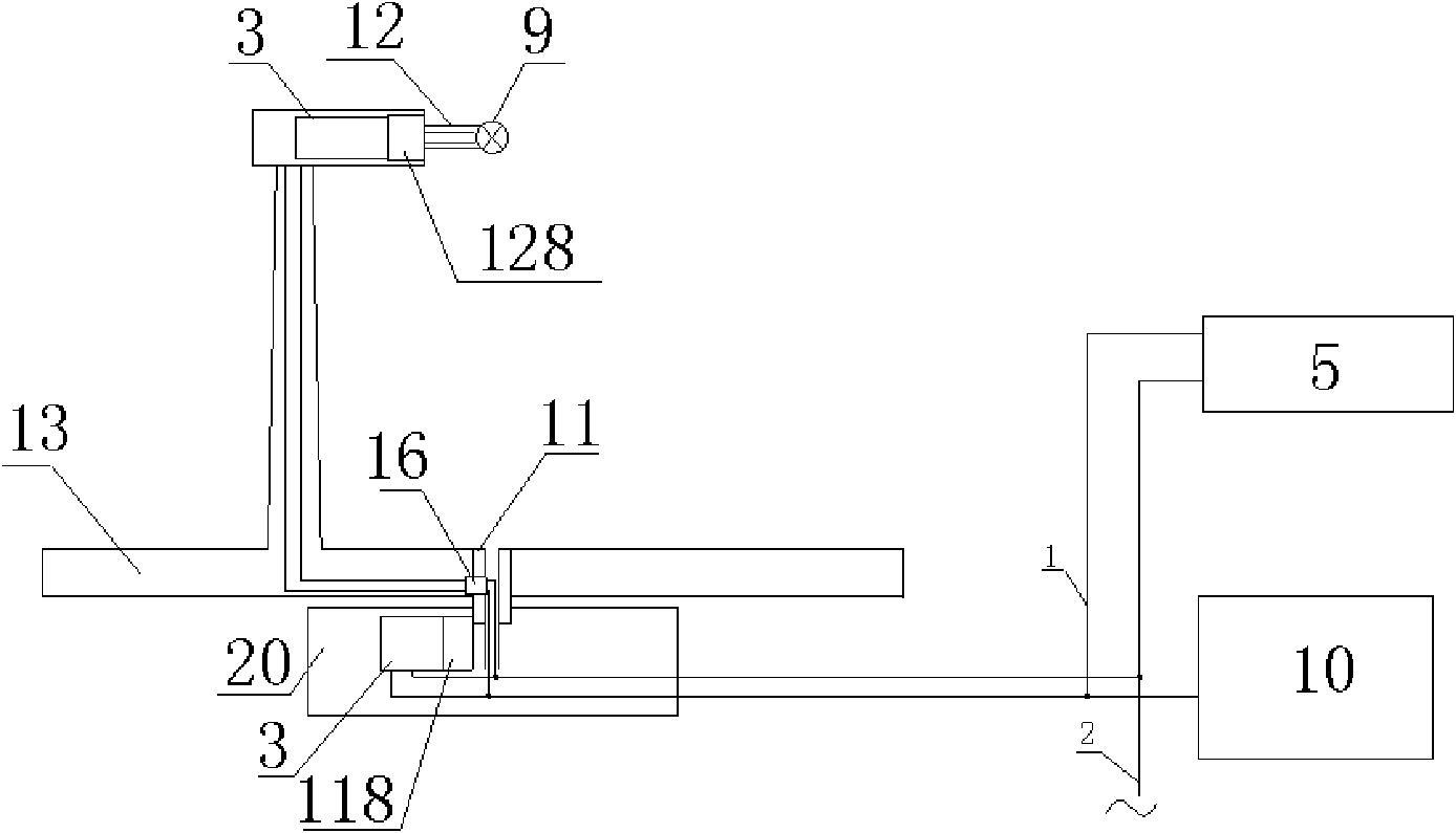
[0038] Embodiment 1: The goniophotometer system of this embodiment, as shown in FIG. 1 , includes a rotary table, an optical signal sampling unit, a unit host computer 10 and a display operation module 5 . The rotary table includes a base 20, on which a first rotating shaft 11 is mounted, on which a rotating arm 13 is connected, on which a second rotating shaft 12 is installed, driving the first rotating shaft 11 The first motor 118 is located on the base 20, and the second motor 128 driving the second rotating shaft 12 is located next to the second rotating shaft 12 on the rotating arm. A motion control module 3 electrically connected to the first motor 118 is arranged beside the first motor 118 on the base, and a motion control module 3 electrically connected to the second motor 118 is arranged beside the second motor 128 on the rotating arm. As shown in Figure 9, the motion control module 3 includes a control unit 3-1 with a microprocessor, a dedicated motor driver 3-3, a m...

Embodiment 2

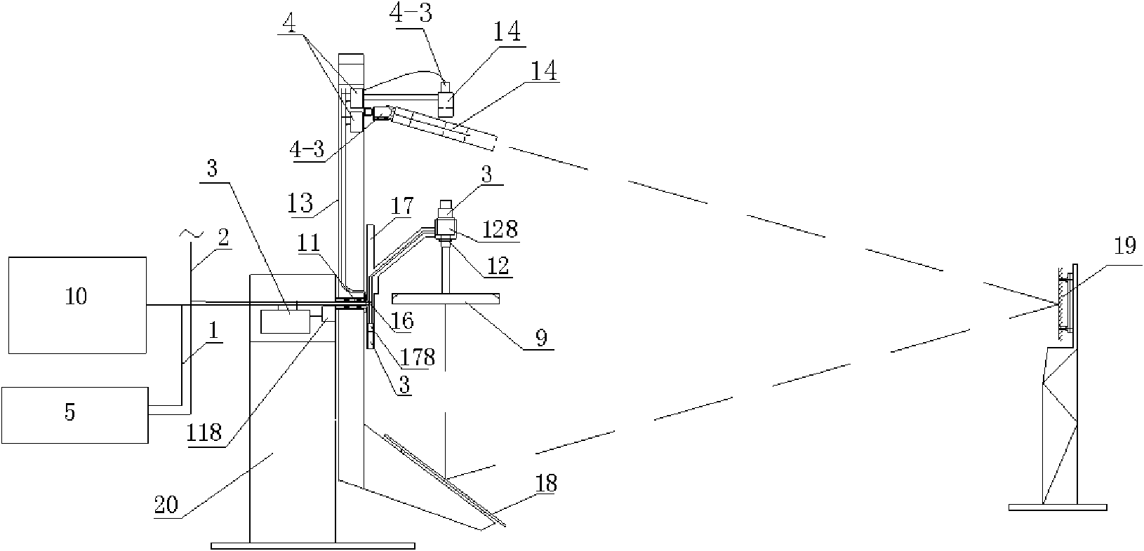
[0045] Embodiment 2: The goniophotometer system of the present embodiment, as shown in FIG. 2 , the rotary table includes a base 20 on which the first rotating shaft 11 and the first motor 118 driving the first rotating shaft 11 are installed. , the first rotating shaft 11 is connected with a rotating arm 13 . One end of the rotating arm 13 is provided with a rotating reflector 18, and the other end of the rotating arm is provided with two optical signal sampling units 14, and two optical radiation measurement modules 4 connected to the two optical signal sampling units are respectively arranged on the rotating arm. 13 on this end. The base 20 is also fixedly connected with a translation mechanism 17, the second rotating shaft 12 is mounted on the translation mechanism 17, the third motor 178 driving the translation mechanism 17 and the motion control module 3 connected thereto are also installed on the translation mechanism 17 , the up and down movement of the translation me...

Embodiment 3

[0049] Embodiment 3: the goniophotometer system of this embodiment, as shown in Figure 3, is provided with the second remote control module 6 on the rotating arm 13, and the I / O line of the optical radiation measurement module 4 on the rotating arm 13 is connected with the second The remote control module 6 is connected, and the first remote control module 7 matched with the second remote control module 6 is arranged near the host computer 10 and electrically connected with the host computer 10 . As shown in Figure 12, the first remote control module 7 and the second remote control module 6 include a signal processing circuit 6-1 with a microprocessor, a radio receiving and transmitting device 6-2, and a power supply unit 6 that provides working power for the remote control module -3, the radio receiving and transmitting device 6-2 is electrically connected with the signal processing circuit 6-1 with microprocessor, the radio receiving and transmitting device of the first remot...


PUM


Abstract

The invention relates to a distribution photometer system comprising a base, a first rotating shaft, a second rotating shaft, a plurality of light signal sampling units and an upper computer, wherein the first rotating shaft is positioned on the base and is also connected with a rotating arm; respective control execution modules are arranged near various execution parts of a distribution photometer; each module is internally provided with a microcomputer and a power supply unit; the modules communicate with the upper computer in a wired way or a wireless way through a three-wire, two-wire or wireless digital signal channel, so that the distribution control can be realized; meanwhile, a digital signal channel and a power supply channel in the rotating arm are conducted to the base through a conductive sliding ring arranged on the first rotating shaft. With the measures, the invention greatly reduces connecting leads in the distribution photometer, reduces the interactive interference and the outside interference among the connecting leads, and improves the reliability and the real-time property for data transmission, thereby improving the control and measuring precision of the system and being convenient to maintain and manage the system; meanwhile, the invention also solves the winding problem of a distribution photometer in the operation process.

Description

technical field [0001] The invention belongs to the field of optical testing, and in particular relates to a distribution photometer system which reduces wiring, reduces signal interference and signal loss, and improves the reliability of control and measurement. Background technique [0002] The goniophotometer is mainly used to measure the luminosity of the measured light source at various angles in space. It is an instrument integrating optical, mechanical and electrical technologies. [0003] There are various types of goniophotometers. The mechanical part mainly includes optical radiation measuring instruments and a rotating table for clamping the measured light source and making the measured light source and the optical radiation measuring instrument sampling device (such as photometric probe) relatively rotate. The relative rotation between the measured light source and the sampling device of the optical radiation measuring instrument is realized by the rotation of th...

Claims


Application Information

Patent Timeline
Patent Type & Authority Applications(China)
IPC IPC(8): G01J1/02
Inventor 潘建根
Owner 远方谱色科技有限公司
Why Eureka
Try Eureka