Real fire drilling system for emergency rescue

A technology of emergency rescue and real fire, applied in the field of emergency rescue, can solve the problems of not being able to truly simulate the fire scene environment, poor training safety, not clearing, etc., and achieve the effect of increasing the difficulty of drills, improving the handling of accidents, and improving the sense of reality

Active Publication Date: 2012-05-02
山西虹安科技股份有限公司
View PDF0 Cites 1 Cited by
  • Summary
  • Abstract
  • Description
  • Claims
  • Application Information

AI Technical Summary

Problems solved by technology

This requires the rescuers to have extremely high professional skills and psychological qualities. It is far from enough to rely on the accumulation of these skills and qualities in actual combat, and ordinary physical training cannot actually improve the ability in actual disaster relief. A drill system that truly simulates a fire environment, but the existing drill equipment has a single function and cannot truly simulate a fire scene environment. The flame simulation is only realized by traditional fuel oil and wood, which will generate a lot of pollution and make the fire uncontrollable, and the training safety is poor
After this traditional simulated flame is extinguished, burning garbage will be produced, and the next drill cannot be carried out without cleaning

Method used


Image

  • Real fire drilling system for emergency rescue
  • Real fire drilling system for emergency rescue
  • Real fire drilling system for emergency rescue

Examples


Embodiment 1

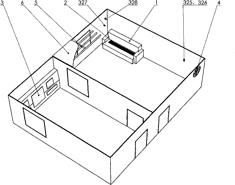
[0022] Such as figure 1 Shown is a three-dimensional schematic diagram of the present invention. The rescue and rescue real fire drill system consists of the main structure of the combustible substance 1, the combustion device 2, the control and monitoring system 3, the fan 4, and the flashover device 5. The main structure of the combustible substance 1, the combustion device 2, the fan 4, and the flashover device 5 are installed in In the training room, the control and monitoring system 3 is installed in the control room. The control room and the training room are two adjacent rooms with a height of 4.5m and an area of ​​10m×5m and 10m×10m respectively. The ceiling 6 of the training room is equipped with 1cm steel plate.

[0023] The combustion product main structure 1 is a 1:1 sofa model made of steel plate, and the model has a 30cm×150cm installation opening. The combustion device 2 is installed in the installation opening of the combustion product main structure 1.

[0024] Su...

Embodiment 2

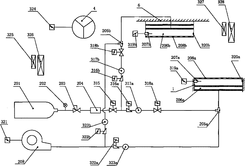
[0042] Such as Figure 4 As shown, the difference between the second embodiment and the first embodiment is that the main structure 1 of the burning material of the second embodiment is a simulated oil tank with a diameter of 1m and a height of 2m, and is installed outdoors, and a smoke simulator 5 is provided under the combustion device 2. , The combustion device 2 is installed vertically, and the smoke simulator 5 can also be controlled by the control terminal provided in the control monitoring system 3. The second implementation example does not have an indoor temperature sensor 325, a combustible gas sensor 326, a fan 4, and a flashover device 5.


PUM


Abstract

The invention relates to a real fire drilling system for emergency rescue, which comprises a comburant main structure, a combustion device, a control monitoring system, an exhaust fan and a flashover device, wherein the comburant main structure, the combustion device, the exhaust fan and the flashover device are installed in a training room; the exhaust fan is installed above the wall surface of the training room and the upper part of the exhaust fan clings to the ceiling; the control monitoring system is installed in a control room; the control room and the training room are two adjacent rooms; steel plates are additionally installed on the ceiling of the training room; and the combustion device comprises a gas source, a pressure gauge, a gas cylinder hand valve, a decompression device, a tee joint, a combustion tray, an ignition device, a net boom, a blower and the like. The simulated disaster environment comprises real flame and smog which improve the reality sensation of drilling.The real fire drilling system for the emergency rescue has automatic control, no pollution and environment protection, ensures the training safety, and can improve the disaster relief capacity of therescue personnel in the training environment simulating an actual combat.

Description

Technical field [0001] The invention belongs to the field of emergency rescue, and relates to an emergency rescue exercise system, in particular to an emergency rescue real fire exercise system. Background technique [0002] At present, fires caused by various reasons cause great harm to human life and property, and if effective and timely rescue can be launched at the initial stage of the fire, the loss of life and property can often be greatly reduced. This requires rescuers to have extremely high professional skills and psychological qualities. These skills and qualities are far from enough to rely on accumulation in actual combat, and ordinary physical training cannot actually improve their ability in actual disaster relief. A drill system that truly simulates the fire environment, while the existing drill equipment has a single function and cannot truly simulate the fire environment. The flame simulation is achieved only by traditional fuel and wood, which will produce a lot...

Claims


Application Information

Patent Timeline
Patent Type & Authority Patents(China)
IPC IPC(8): G09B9/00A62C99/00
Inventor 李新年渠伟秦香果高华
Owner 山西虹安科技股份有限公司
Why Eureka
Try Eureka