Light emitting diode base plate heat radiation structure and manufacture method thereof

A technology of light-emitting diodes and heat dissipation structures, which is applied in the direction of electrical components, electrical solid devices, circuits, etc., can solve the problems of poor reflection effect of aluminum plate, weak welding, difficult process technology, etc., and achieve good light reflection effect, flatness and The smoothness is easy to guarantee and the effect of reducing production costs

Inactive Publication Date: 2010-08-25
FORYOU MULTIMEDIA ELECTRONICS
View PDF5 Cites 6 Cited by
  • Summary
  • Abstract
  • Description
  • Claims
  • Application Information

AI Technical Summary

Problems solved by technology

[0004] In order to solve the problem of poor reflection effect and unevenness of the aluminum plate at the bottom above, a scheme of silver-plating the conductive circuit layer contained on the aluminum substrate and the aluminum plate is proposed, but because the conductive circuit layer is silver-plated, the light-emitting diodes drawn out The soldering of gold wires on the silver-plated conductive circuit layer has the problem of weak soldering
[0005] In order to solve the above problem of weak welding, it is proposed to plate silver on the aluminum plate to improve the reflection effect, and to plate the conductive circuit layer with gold to solve the problem of weak welding. However, due to the difficulty of this process technology, the aluminum substrate with this structure has not been widely used. use

Method used


Image

  • Light emitting diode base plate heat radiation structure and manufacture method thereof
  • Light emitting diode base plate heat radiation structure and manufacture method thereof
  • Light emitting diode base plate heat radiation structure and manufacture method thereof

Examples


Embodiment 1

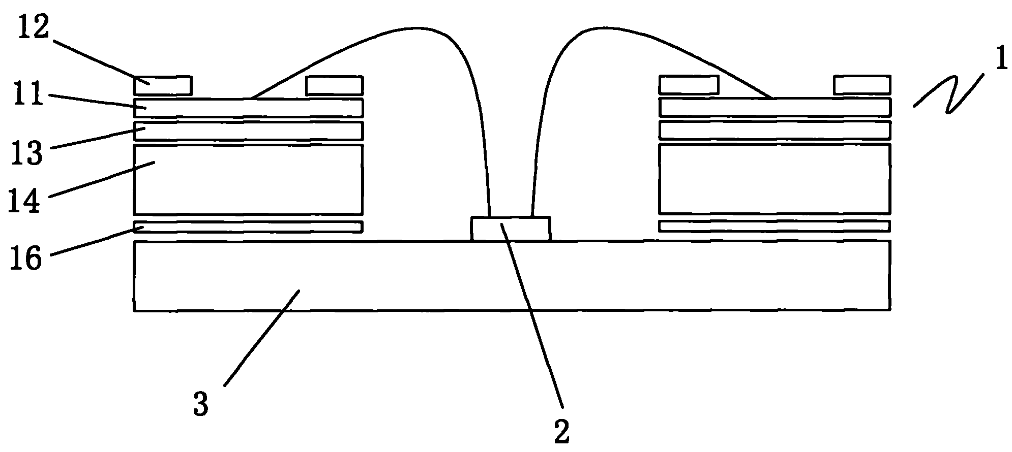
[0026] Embodiment 1: As shown in Figure 3, the heat dissipation structure of the light-emitting diode circuit board disclosed in this embodiment is an improvement on the heat dissipation structure of the conventional light-emitting diode aluminum substrate, which is consistent with the conventional aluminum substrate. The aluminum substrate 1 consists of White oil layer 12 , conductive circuit layer 11 , insulating layer 13 and aluminum substrate 14 .

[0027] Compared with the existing aluminum substrate, the biggest improvement of the aluminum substrate in this embodiment is that the bottom of the aluminum substrate 14 is closely pasted with a heat-dissipating base plate 3 through the heat-conducting adhesive 16, and the material of the base plate 3 can be good for heat dissipation The metal, silicon or ceramics can also be used. A through hole 15 is opened at the position where the light emitting diode 2 is installed on the substrate 14 , the light emitting diode 2 is close...

Embodiment 2

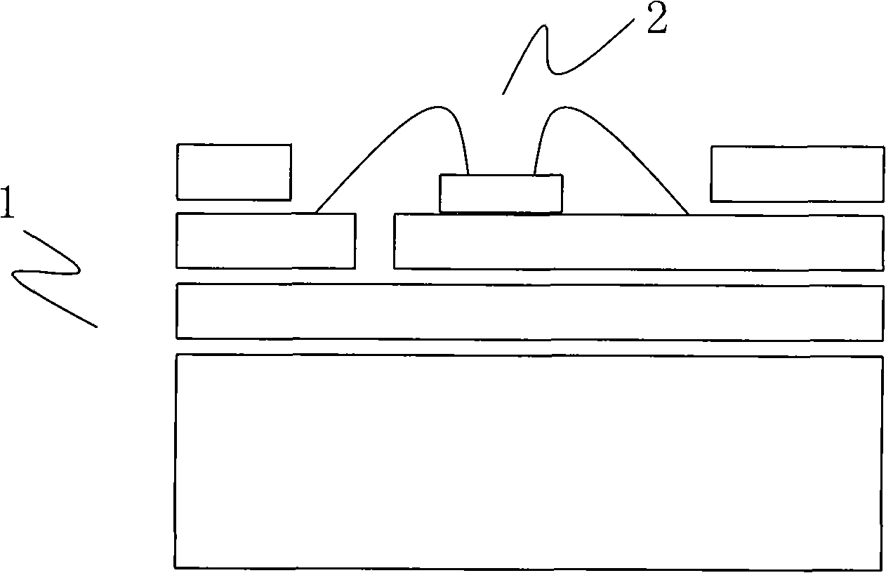
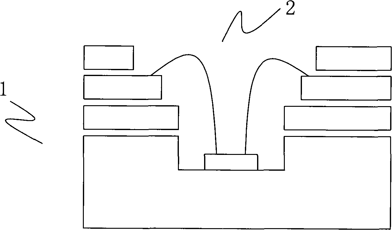
[0035] Embodiment 2: As shown in accompanying drawing 4, the structural principle of this embodiment is consistent with that of Embodiment 1, the difference is that the glass fiber circuit board in the circuit board is improved, and the glass fiber circuit board 1 is from top to bottom The lower layer includes a white oil layer 12, a conductive circuit layer 11 and an insulating layer 13 in sequence, which is consistent with the improvement in the embodiment. A heat dissipation bottom plate 3 is also closely attached to the bottom of the insulating layer 13 through a heat-conducting adhesive 16. The light-emitting diode 2 is preset in the The through holes on the glass fiber circuit board 1 are closely attached to the base plate 3 , and the power lines of the LEDs 2 are also connected to the wiring layer 11 .

[0036] Similarly, the following steps can be used for specific production:

[0037] a. Process the bottom plate according to the size of the circuit board and the distr...


PUM


Abstract

The invention relates to a light emitting diode circuit board heat radiation structure, which comprises a circuit board and a light emitting diode, wherein the light emitting diode is communicated with a circuit of a conductive circuit layer in the circuit board, a heat radiation bottom plate is tightly pasted on the lower surface of the circuit board, a through hole is formed in the position of the circuit board provided with the light emitting diode, and the light emitting diode is pasted on the inner surface of the bottom plate through the through hole. Through the additional arrangement of the heat conductive plate, the structure eliminates the adverse influence caused by self damage of the circuit board and the subsequent manufacture and processing in the prior art, and the light emitting diode can be directly pasted on the heat radiation bottom plate, so the whole base plate has higher heat conduction coefficient, the light ray emitting effect and the heat radiation effect are good, in addition, the manufacture and processing process of the existing circuit board can not be influenced, the bottom plate can be singly processed, the smoothness and the finish degree of the bottom plate can be easily ensured, the processing step is greatly simplified, and the manufacture difficulty is reduced, so the production cost is reduced.

Description

technical field [0001] The invention relates to an improvement of a heat dissipation structure of a substrate. Background technique [0002] In the past, light-emitting diodes were developed to be installed on aluminum substrates as lighting sources. Especially in recent years, as the thermal conductivity of aluminum substrates has gradually increased, the driving current of light-emitting diodes can use a larger current. Furthermore, in order to reduce the volume of the lighting source, the integration degree of the light emitting diodes mounted on the aluminum substrate is originally higher. However, under the higher driving current of the highly integrated lighting source, the light-emitting diode will relatively generate more heat, which will affect other performances due to overheating, and even cause damage to the light-emitting diode. Please refer to Figure 1. [0003] In order to further increase the thermal conductivity of the aluminum substrate and reduce its the...

Claims


Application Information

Patent Timeline
Patent Type & Authority Applications(China)
IPC IPC(8): H01L33/48H01L33/62H01L33/64
CPCH01L2224/48091
Inventor 贺能陈建平
Owner FORYOU MULTIMEDIA ELECTRONICS
Why Eureka
Try Eureka