Cone sand making machine and sand making method

A technology of sand making machine and cone, which is applied in the direction of grain processing, etc., can solve the problems of low sand making yield, high equipment cost, high sand making cost, etc., and achieve the effect of high sand making efficiency, long service life and low cost

Active Publication Date: 2012-11-21
ZHEJIANG SHUANGJIN MACHINERY HLDG
View PDF1 Cites 44 Cited by
  • Summary
  • Abstract
  • Description
  • Claims
  • Application Information

AI Technical Summary

Problems solved by technology

Its shortcomings: first, low efficiency and high energy consumption; second, the way of sand making is iron hitting stone, that is, the machine throws stones on the high-strength alloy wall to break the stones to make sand, so the finished sand is The rate is low, but the equipment cost is high and the cost of sand making is high

Method used


Image

  • Cone sand making machine and sand making method
  • Cone sand making machine and sand making method
  • Cone sand making machine and sand making method

Examples


Embodiment 1

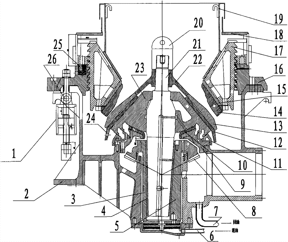
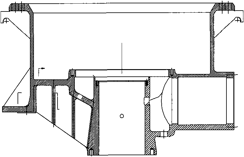
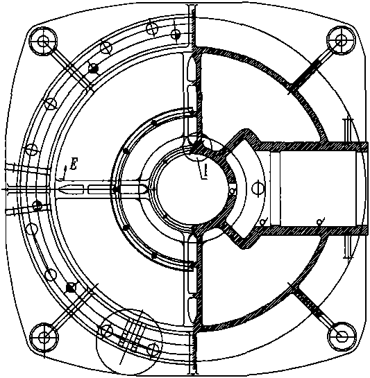
[0023] Embodiment 1: with reference to attached Figure 1-15 . Conical sand making machine, 8 large bevel gears are set on the eccentric shaft sleeve 5, the eccentric shaft sleeve 5 is set in the shaft hole in the center of the lower casing 2 through the copper sleeve 3, and the main shaft 21 is located in the eccentric shaft sleeve 5 through the inner copper sleeve 4 And the main shaft 21 is driven to swing by the eccentric shaft sleeve 5, the spherical seat 9 is located on the shell support ring of the positioning shaft hole in the lower casing 2, the moving cone 23 is set on the main shaft 21 through the spherical copper tile 10 and is driven by the main shaft 21 The cone 23 swings, and an oil film is placed between the contact surfaces of the movable cone 23 and the spherical copper tile 10 . The moving sleeve bushing 12 is set on the conical surface of the moving cone 23, the anti-friction moving sleeve 13 is set on the conical surface of the moving sleeve bushing 12, th...

Embodiment 2

[0032] Embodiment 2: On the basis of Embodiment 1, the sand making method of the conical sand making machine, when making sand, the oil cylinder located outside the upper casing 16 pushes the adjusting screw sleeve 17, so that the lower screw sleeve located in the adjusting screw sleeve 17 The gap formed by the wall surface of the anti-wear fixed sleeve 14 on the horn wall and the wall surface of the anti-wear movable sleeve 13 is just the upper limit of the required sand grain diameter. Start the hydraulic workstation so that the lubricating oil under pressure enters the main shaft 21 through the bottom cover type plane bearing And the horizontal oil outlet in the main shaft injects between the contact surface of the movable cone 23 and the spherical copper tile 10 and between the main shaft 21 and the 4 surfaces of the inner copper sleeve, so that the contact surface of the movable cone 23 and the spherical copper tile 10, the contact surface of the main shaft 21 and the The ...


PUM


Abstract

The invention relates to a cone sand making machine and a sand making method with high efficiency, low energy consumption and high sand making yield. A big bevel gear is sleeved on an eccentric shaft sleeve which is sleeved in an axle hole in the centre of a lower shell through a copper jacket; a main shaft is positioned in the eccentric shaft sleeve through an inner copper sleeve; a spherical seat is positioned on a shell supporting ring of the positioning axle hole in the lower shell; a movable cone is sleeved on the main shaft through a spherical copper bearing bush and pushed by the main shaft to swing; a movable sleeve bushing is sleeved on the conical surface of the movable cone; an anti-wear movable sleeve is sleeved on the conical surface of the movable sleeve bushing; an inserteris sleeved on the main shaft and locked by a locking nut; an upper shell and the lower shell are connected together and three or more adjusting oil cylinders are arranged between the outer turned edges of the upper and lower shells; the inner wall of the upper shell is provided with annular spiral sawteeth which are engaged with those on the outer wall of an adjusting screw sleeve; and the adjusting screw sleeve has a double-trumpet structure, the lower trumpet-shaped wall of the adjusting screw sleeve is connected with an anti-wear fixed sleeve through a fixed sleeve bushing, and the upper trumpet-shaped wall of the adjusting screw sleeve is used for supporting a hopper assembly.

Description

technical field [0001] The invention relates to a conical sand making machine with high efficiency, low energy consumption and high sand making rate and a sand making method, belonging to the field of sand making machine manufacturing. Background technique [0002] CN101362112A, title "a kind of dry type sand making method and the dry type sand making machine used", including a hollow crushing working chamber, a hollow dust removal working chamber is arranged below the crushing working chamber, the upper end of the feeding channel is connected with the feeding The lower end of the feeding channel is located in the dust removal working chamber, and there is also a vent on the dust removing working chamber. The bottom surface of the dust removal working chamber is provided with an outlet; the dust suction component is sealed and connected with the lower end of the air duct after passing through the outlet, or the dust suction component is sealed and connected with the air vent...

Claims


Application Information

Patent Timeline
Patent Type & Authority Patents(China)
IPC IPC(8): B02C2/04
Inventor 胡祖尧
Owner ZHEJIANG SHUANGJIN MACHINERY HLDG
Why Eureka
Try Eureka