[0038] The present invention will be further described below with reference to the embodiments of the accompanying drawings.
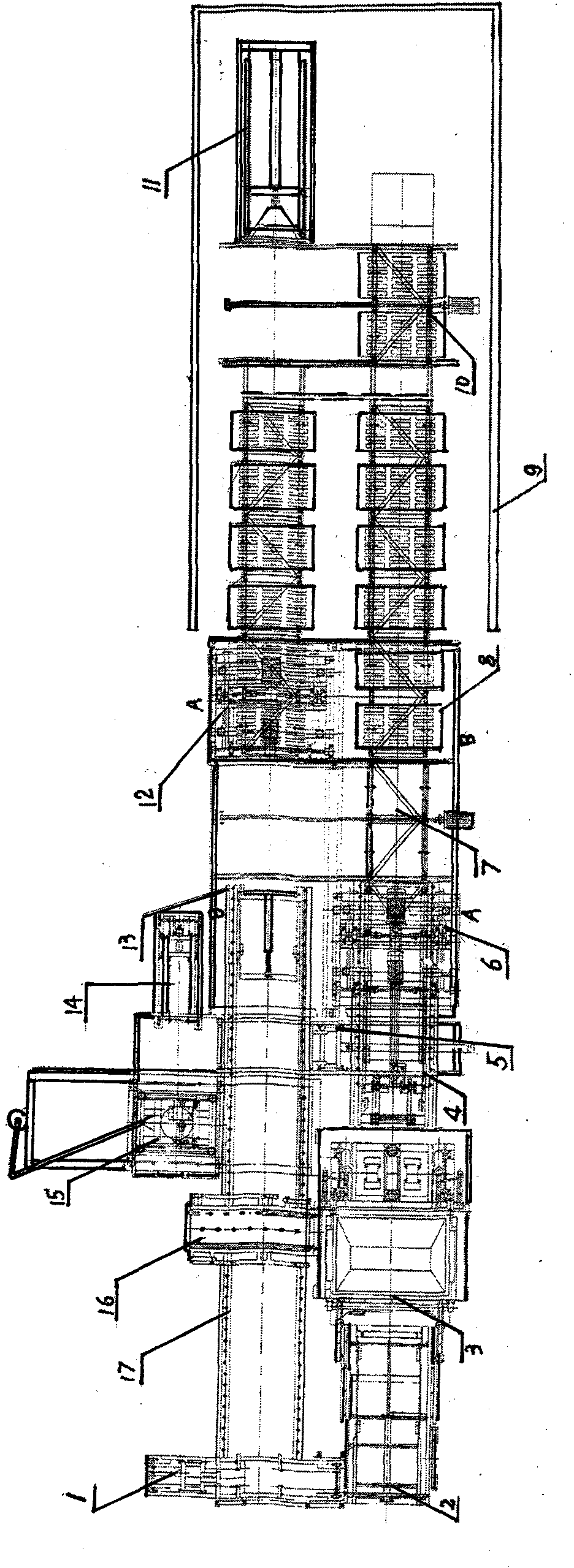
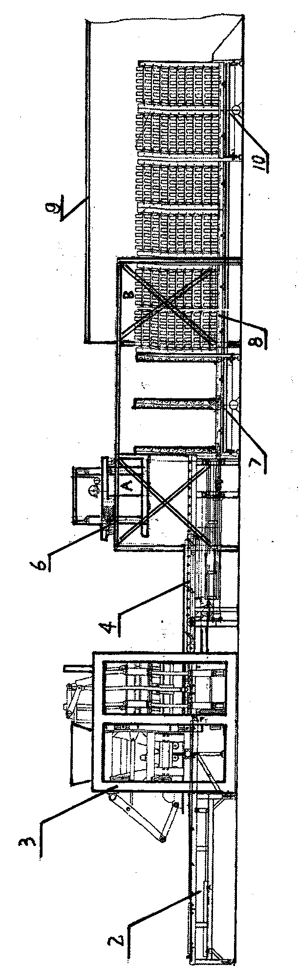
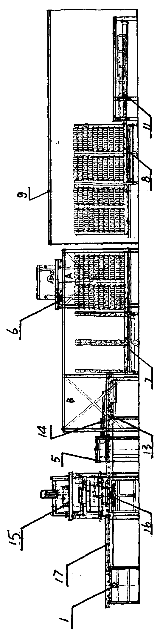
[0039] see attached figure 1 , figure 2 , image 3 The mobile block solar maintenance and production line shown includes a trigger feeder 2, a forming machine 3, a bridge 4, a plate loading machine 6, a front traverse mechanism 7, and a layered maintenance trolley 8, which are arranged in sequence in the longitudinal direction. On the entrance side of the chamber 9, the terminal end of the solar energy collecting chamber 9 has a rear traverse propulsion mechanism 10 and a longitudinal propulsion mechanism 11 on one side; 13. Brick pushing machine 5, plate turning machine 16, dry area running frame 17 and plate feeding machine 1 arranged horizontally; the plate feeding machine 1 is connected with the plate feeding machine 2; Block palletizing robot 15.
[0040] See Figure 4 The structure of the brick pusher is given. The brick pusher 5 of this embodiment includes a rail 18 and a movable push frame 19 mounted thereon; one side of the movable push frame 19 is connected to a fixed telescopic oil cylinder 20 . Mainly used for the separation of blocks and pallets. The brick pusher is connected with the splitter across the transition bridge.
[0041] See Figure 5 The structure of the loading and triggering machine is given. The plate loading machine 6 and the plate unloading machine 12 in this embodiment include a frame 21 with loading and unloading stations in A and B areas, and a frame-body traveling cart 33 and a frame body are installed on the horizontal beam of the frame. A traveling motor 30 is installed, two sets of guide frames 32 are fixed on the frame body of the travelling carriage 33, and separation forks 27 are symmetrically arranged at the lower ends of both sides of the frame body of the travelling carriage 33; The frame type lifting frame 23 of 22 has a beam 24 and a bracket 25 at the upper and lower ends of the lifting frame 23, and a chain 29 is installed on the beam 24 and the bracket 25 to bypass the guide wheel 31 and the lifting motor set on the frame body of the traveling vehicle 33. The sprocket on 30 is connected with the bracket 25 on the lifting frame 23; a number of overturned claws 34 are installed on the coaxial 26 set at the bottom of the bracket 25 on both sides; The top pawl 35 is provided at a position 28 corresponding to any one of the holding pawls 34 . When in the A-zone loading station, the claws on the lifting frame are open. After starting the lifting motor, the lifting frame is controlled by the chain drive to move down until the pallets carrying the blocks touch each other, the claw turns over and avoids by itself, and then continues to descend to the lowest level of the pallet, and then the claw opens and then rises up. The pallets carrying the blocks move upward together. After the travel motor drives the traveling cart to move to the unloading station in the B area, repeat the above actions to move the lifting frame down to the layered moving frame. Unload the pallet and continue to move down until the claw touches. When it touches the top claw, it acts on the support claw and turns it into a vertical state and starts the lifting motor to control the lifting frame to move up until it touches the separation fork, so that the support claw is opened, and the traveling motor is started to drive the traveling cart to return to the installation station in the A area. Repeat the above actions.
[0042] It should be noted that the trigger loader 6 and the trigger release 12 have the same structure, but are only installed on two workstations. The plate loading machine 6 is located on the entrance side of the solar collecting chamber, and stacks the tiered maintenance vehicle; and the unloading trigger 12 is located on the exit side of the solar collecting chamber, which unloads the pallet with blocks from the tiered maintenance vehicle. , send to the next process.
[0043] Image 6 The front traverse mechanism is given. The front traverse mechanism 7 of this embodiment includes a moving frame 36 with rollers, and a guide rail 37 on which a layered mobile maintenance vehicle is arranged; the moving frame 36 is installed on the guide rail (not marked in the figure); The lower central end of the moving frame 36 is provided with a nut 38 which is installed and matched with the lead screw 39 at the output end of the motor. Its function is to return the unloaded layered mobile maintenance vehicle to the area between A and B of the plate loader through the front traverse mechanism after the pallet with blocks is unloaded by the unloading trigger, and passes through the bridge. 4 The forward push mechanism set at the bottom pushes the layered mobile maintenance truck to the B area of the plate loader for stacking.
[0044] Figure 7 The layered maintenance vehicle structure is given. The layered maintenance vehicle 8 of this embodiment includes a frame body with two independent spaces formed by a vertical frame 40 and a beam 41 . Rollers 42 are arranged on the beam 41 to form a maintenance vehicle. In this embodiment, the vertical frames 40 are mounted on the beams 41 in a “mountain” shape, and the inner sides of each pair of vertical frames 40 corresponding to each other are symmetrically distributed from top to bottom with hinged overturning support devices, and the most The lower support device is connected with a linkage mechanism.
[0045] The support device described in this embodiment has a support claw 44, which is installed on the vertical frame 40 through a pin shaft 45, and a protruding hinge seat 47 at the rear of the support claw 44, which is connected to the rear of the support claw through the hinge shaft. The supporting plate 46 is hingedly connected; the vertical frame 40 located between the supporting plate 46 and the head of the claw 44 has a blocking shaft 43 that limits the lateral displacement of the supporting plate 46 . The link mechanism involved in the above includes a swing rod 48 connected to the beam 41 of the frame body through the hinge shaft 50; one end of the swing rod 48 is hinged with the support plate 46 installed at the bottom of the vertical frame; One end is provided with a vertical pressing rod 49 .
[0046] Figure 8 The solar collection chamber is given. The solar energy collecting chamber 9 of this embodiment includes a frame 51, and a heat-insulating wall formed by a polystyrene board 52 is installed around the bottom of the frame 51; a double-layer hollow solar panel 53 is installed on the frame 51 of the heat-insulating wall to form a collection two sets of guide rails 54 are arranged side by side in the collecting chamber. In the above, the cross section of the solar collecting chamber is a positive arc.
[0047] Figure 9 The rear traverse propulsion mechanism is given. The rear traverse propulsion mechanism 11 of this embodiment includes a moving frame 55 with rollers, and a guide rail 56 on which a layered mobile maintenance vehicle is arranged; the moving frame 55 is installed on the guide rail 56 through the upper and lower rollers; The lower central end of the frame 55 is provided with a nut 57 to be installed and matched with the lead screw 58 of the motor output end; a push-back mechanism is connected to the reversing side perpendicular to the guide rail frame; the push-back mechanism has a frame 59 corresponding to the side of the moving frame 55 At the end, an oil cylinder 60 is installed on it to connect with the moving push frame 61, and the guide frame 62 connected to the moving push frame 61 is installed on the rollers on the frame 59.
[0048] Figure 10 The apportioner structure is given. The apportioner 12 of this embodiment includes a pallet return frame 63 connected to the dry area running frame 17 ; a movable push frame 64 is installed at the entry end of the pallet return frame 63 ; one end of the movable push frame 64 is connected to a propelling oil cylinder 65 connections. The spreader 12 is located at the B-area station where the trigger is unloaded. It is mainly to use the unloading trigger to unload the blocks and trays carried on the layered maintenance vehicle from the exit of the solar energy collection room and send them to the apportioning machine on the B area, and push the blocks and pallets to the dividing machine through the dividing machine. On the platform of the brick pusher in the next process, the bricks are separated from the pallet by the brick pusher, and the blocks are sent to the closing platform of the closing machine;
[0049] Figure 11 The structure of the shrinking machine is given. The folding machine 14 of this embodiment includes a folding platform (not marked in the figure) connected to the pallet return frame 63; a propelling oil cylinder 67 is provided on the frame 66 connected to one side of the folding platform to connect with a moving push frame 68 ; The mobile push frame 68 is mounted on the rack rail 69 by having rollers on it. The stacking machine 13 is connected with the block stacking robot in the next process, and is used for sending the blocks to the block stacking robot in the next process.
[0050] Figure 12 The structure of block stacking manipulator is given. The block stacking manipulator 15 in this embodiment includes a frame-type frame 98 with a certain space and height symmetrically arranged, on which a mobile trolley 96 with rollers is movably installed; one side of the mobile trolley 96 is connected with a hinged crank The rod 97 is hingedly connected; the crank link 97 is connected to a drive motor 99 mounted on one end of the frame. In this way, the reciprocating swing action of the crank connecting rod 97 is controlled by the driving motor 99 to move the carriage 96 back and forth horizontally. A turbo reducer 70 is arranged on the moving carriage 96, and a sprocket 71 is installed at the output end thereof. A chain 72 is installed on the sprocket 71, so that one end of the chain 72 bypasses the guide wheel 73 on the mobile trolley 96 and is connected to the beam 106 at the upper end of the lifting guide frame 74; the other end of the chain 73 is installed on the lower end of the lifting guide frame 74. The rotating device on the beam 105 is connected with the lifting mechanism composed of guide wheels 75 on both sides of the lifting guide frame 74 . The rotating device includes setting a rotating movable outer sleeve 77 on the horizontal end of the lower end beam 105 of the lifting guide frame 74 to connect with the movable inner sleeve 78 on the main body; the movable outer sleeve 77 is installed on the lower end beam 105. The fixed sleeve 82 A ball 79 is arranged between the mating parts of the motor; the rotating seat 83 is installed on the fixed sleeve 82, and the motor 100 is installed on it; the screw 80 connected to the output end of the motor 100 and the nut 81 on the eccentric position of the movable sleeve 77 are assembled and formed. A rotating body; a dial shaft 101 is symmetrically arranged at the lower end of the movable inner sleeve 78 in this embodiment, and the dial shaft 101 is connected to the frame 102 in the associated clamping mechanism through the dial shaft 101 . When the rotating device rotates, the screw 80 is used to drive the nut 81 to drive the inner sleeve 78 to rotate, so as to control the rotation of the clamping mechanism. The clamping mechanism in this embodiment includes a frame 102, and movable splints 87 are installed on four laterally arranged sliding shafts 104 at the lower part of the frame 102; 84; There is a pressure sensor 88 and an encoder 89 between the palm surface 84 and the movable splint 87 in two directions; a central shaft 95 is provided in the central sleeve 94 on the frame 102; The nut 91 is installed and matched with the screw 92 connected to the motor 103; the motor 103 is installed on the rotating seat 93 at the eccentric position on one side of the frame 102; the lower end of the central shaft 95 is fixedly installed with a synchronizer 90; An adjustment rod 86 is hinged with each movable splint 87 in the direction.
[0051] In the above, the synchronizer 90 is a cross structure body, other than that, it can be selected as a disc body.
[0052] In the above, the related horizontal displacement device includes a mobile trolley on which two sets of rollers are installed; a turbo reducer and a sprocket with an output end are installed on the mobile trolley.
[0053]In the above, the rotating device has a vertical frame and its outer side is symmetrically arranged with support wheels; the horizontal end of the vertical frame is provided with an inner casing, a rotating seat is installed on the inner casing, and a rotating casing is installed on the balls distributed on the rotation; An eccentric position of the rotating sleeve is provided with a nut to fit with a screw rod connected to a motor mounted on the rotating sleeve. When the motor drives the screw to rotate, the rotation angle of the control nut and the body changes, the screw has strong self-locking ability, and the resistance of the nut is greater than the rotational inertia of the screw at the moment of power failure, so the rotation can be stopped immediately. , with accurate positioning.
[0054] In the above, the lifting device includes a chain, one end of which is connected to the outer casing of the rotating device; Due to the use of chain transmission mechanism, the lifting and positioning are accurate, the self-locking ability is strong, and the transmission is stable. In the above, the clamping mechanism includes a frame and a chassis provided thereon, and a movable splint is arranged on the shaft rod arranged on the periphery of the chassis, and the inner side of the movable splint is connected with a palm surface by a spring; pressure sensor and encoder; a synchronizer center shaft is arranged in the center of the chassis; one end of the pendulum rod connected to the upper end of the synchronizer center axis is hinged with a nut to be installed and matched with the screw connected to the motor installed on the side of the chassis to rotate; A rotary synchronizer is installed on the lower end of the central shaft of the synchronizer, which is connected with the movable splint through a hinged adjustment rod. The frame of the clamping mechanism is connected to the axis of symmetry on the rotating device. When the screw drives the nut to move, the action pendulum rod drives the central shaft of the synchronizer and the rotary synchronizer to rotate, and at the same time pulls the adjustment rod and the movable splint to move inward synchronously to realize the tightening of the manipulator. When the palm surface falls and encounters resistance, the pressure sensor makes the manipulator rise through calculation; when the tightening force formed between the palm surface and the block is not enough to cause displacement, the encoder instantly transmits the sensing result to the pressure sensor and sends a boost signal , the screw continues to rotate to control the displacement of the movable splint until the encoder no longer rotates, that is, to ensure that there is enough tightening force, and the block will not be damaged.
[0055] The pressure sensor and encoder referred to in the present invention are purchased products.