Air conditioner in machine room

A computer room air conditioner and compressor technology, which is applied to refrigerators, refrigeration safety arrangements, refrigeration components, etc., can solve the problems of adjusting the area of ​​the evaporator, reducing the cooling capacity, and causing local hot spots, so as to reduce the area of ​​the evaporator and prevent compression Machine overheating, the effect of precise control

Active Publication Date: 2010-09-01
EMERSON NETWORK POWER CO LTD
View PDF0 Cites 16 Cited by
  • Summary
  • Abstract
  • Description
  • Claims
  • Application Information

AI Technical Summary

Problems solved by technology

Among them, the first method is to directly operate the cooling mode to achieve dehumidification; this method will generate a large cooling capacity while dehumidifying. In order to maintain the temperature of the computer room within a certain range, it is often necessary to turn on the electric heating at the same time to compensate for the temperature drop. , not only consumes a lot of energy, but also takes a long time to dehumidify
[0003] The second method is to achieve dehumidification by reducing the area of ​​the evaporator; by reducing the area of ​​the evaporator, the evaporation temperature is lowered, and the cooling capacity is also reduced compared with the first method while increasing the dehumidification capacity, so it can consume more energy. Less electric heating energy consumption, but this method requires accurate calculation of the reduced area of ​​the evaporator to avoid freezing of the evaporator under low temperature conditions and achieve the purpose of increasing the dehumidification capacity, and different computer room conditions require dehumidification The situation is different, it is impossible to calculate and adjust the evaporator area every time
[0004] The third method is to achieve dehumidification by reducing the air volume of the evaporator; the effect of the second method can basically be achieved by reducing the air volume of the evaporator, but in some medium and large computer rooms, the distribution of air flow is caused by the reduction of air volume. Uneven, can cause localized hot spots

Method used


Image

  • Air conditioner in machine room
  • Air conditioner in machine room

Examples


Embodiment Construction

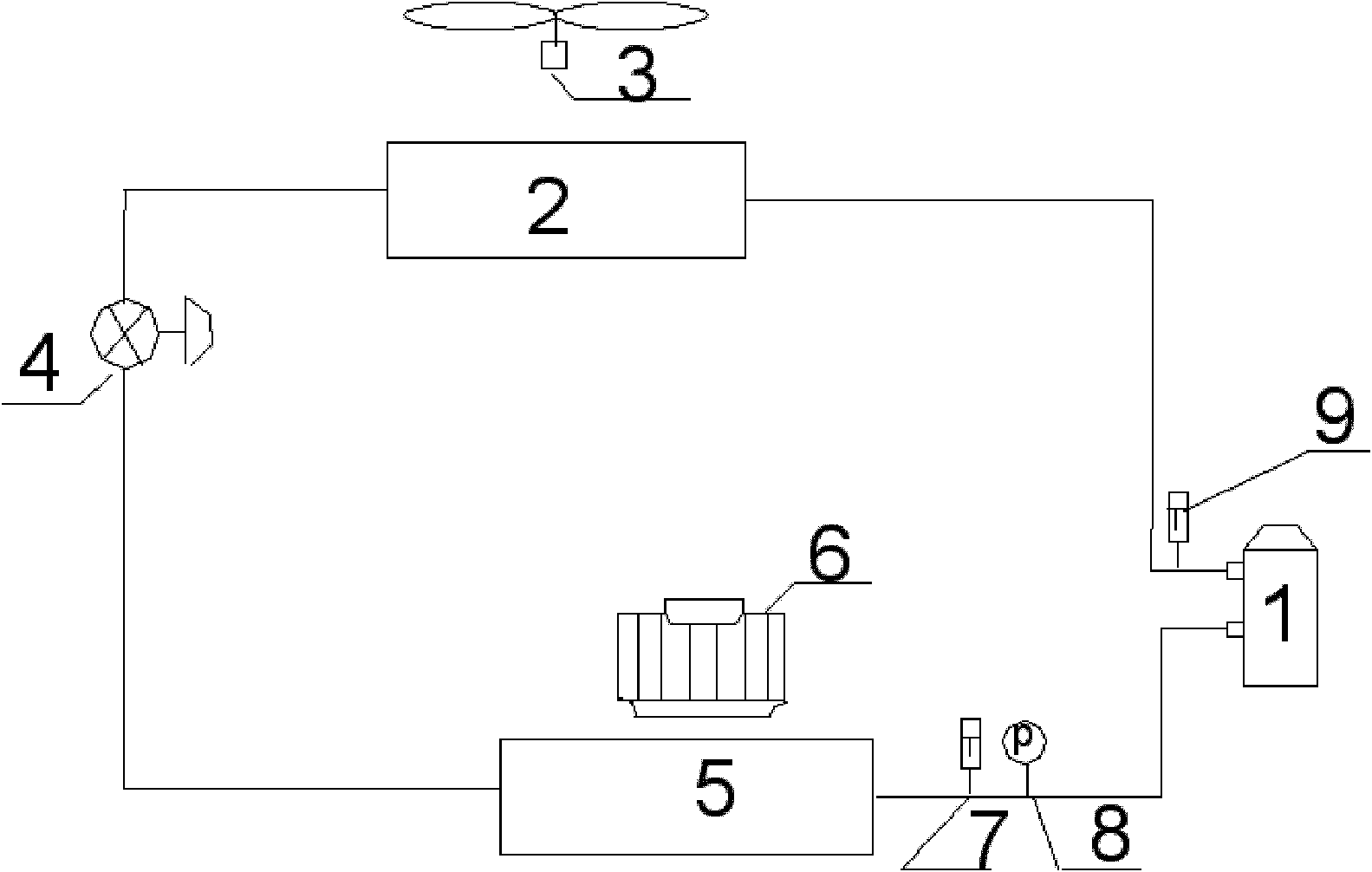
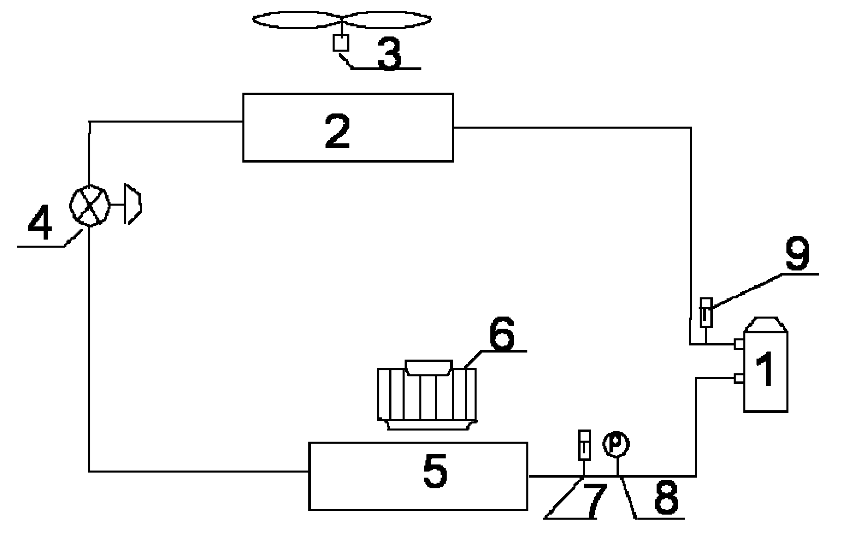
[0019] exist figure 1 In the preferred embodiment shown, the computer room air conditioner of the present invention includes a compressor 1, a condenser 2, an outdoor fan 3, an expansion valve 4, an evaporator 5, an indoor fan 6, a second temperature sensor 7, a pressure sensor 8, a first Temperature sensor 9 and control system (not shown).

[0020] As shown in the figure, the compressor 1 , the condenser 2 , the expansion valve 4 and the evaporator 5 are sequentially connected through pipelines and connected end to end to form a pipeline loop, and refrigerant circulates in the pipelines. Wherein, the refrigerant may be water or ethylene glycol. The outdoor fan 3 and the indoor fan 6 are installed next to the condenser 2 and the evaporator 5 respectively, and are used to blow air to the condenser 2 and the evaporator 5 to increase the air circulation rate and improve the condensation and evaporation efficiency.

[0021] A second temperature sensor 7 and a pressure sensor 8 a...


PUM


Abstract

The invention relates to an air conditioner in a machine room, comprising a compressor (1), a condenser (2), an expansion valve (4) and an evaporator (5) which are electrically connected in sequence to form a loop; the air conditioner also comprises a pressure sensor (8), a first temperature sensor (9) and a control system, wherein the pressure sensor (8) is used for measuring the suction pressure of the evaporator (5); the first temperature sensor (9) is used for measuring the exhaust temperature of the compressor (1); the control system is connected with the pressure sensor (8), the first temperature sensor (9) and the expansion valve (4) to collect a suction pressure signal and an exhaust temperature signal and controls the expansion valve (4); and in a dehumidification state, the control system controls the expansion valve (4) to run towards a closing direction when the exhaust temperature is smaller than or equal to a preset temperature value until the measured suction pressure is not larger than a preset pressure value. In fact, the final suction pressure is larger than or equal to the preset pressure value.

Description

technical field [0001] The invention relates to an air conditioner for a computer room, and more specifically relates to an air conditioner for a computer room capable of rapid dehumidification. Background technique [0002] There are three commonly used dehumidification methods for computer room air conditioners. Among them, the first method is to directly operate the cooling mode to achieve dehumidification; this method will generate a large cooling capacity while dehumidifying. In order to maintain the temperature of the computer room within a certain range, it is often necessary to turn on the electric heating at the same time to compensate for the temperature drop. , not only consumes a lot of energy, but also takes a long time to dehumidify. [0003] The second method is to achieve dehumidification by reducing the area of ​​the evaporator; by reducing the area of ​​the evaporator, the evaporation temperature is lowered, and the cooling capacity is also reduced compare...

Claims


Application Information

Patent Timeline
Patent Type & Authority Applications(China)
IPC IPC(8): F25B49/02
Inventor 殷海明吴刚
Owner EMERSON NETWORK POWER CO LTD
Why Eureka
Try Eureka