
Self-cleaning wiresaw apparatus and method

a wiresaw and self-cleaning technology, applied in metal working apparatus, manufacturing tools, working accessories, etc., can solve the problems of affecting the performance of the wiresaw, affecting the service life of the wiresaw, so as to prevent undesirable encrustation of the moving parts and maintain the moisture level

Inactive Publication Date: 2012-01-12
CABOT MICROELECTRONICS CORP
View PDF27 Cites 8 Cited by
  • Summary
  • Abstract
  • Description
  • Claims
  • Application Information

AI Technical Summary

Benefits of technology

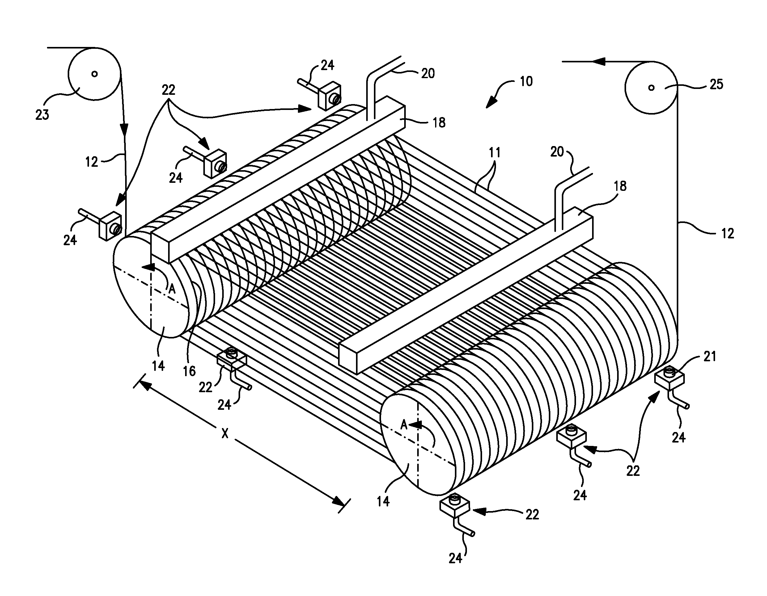
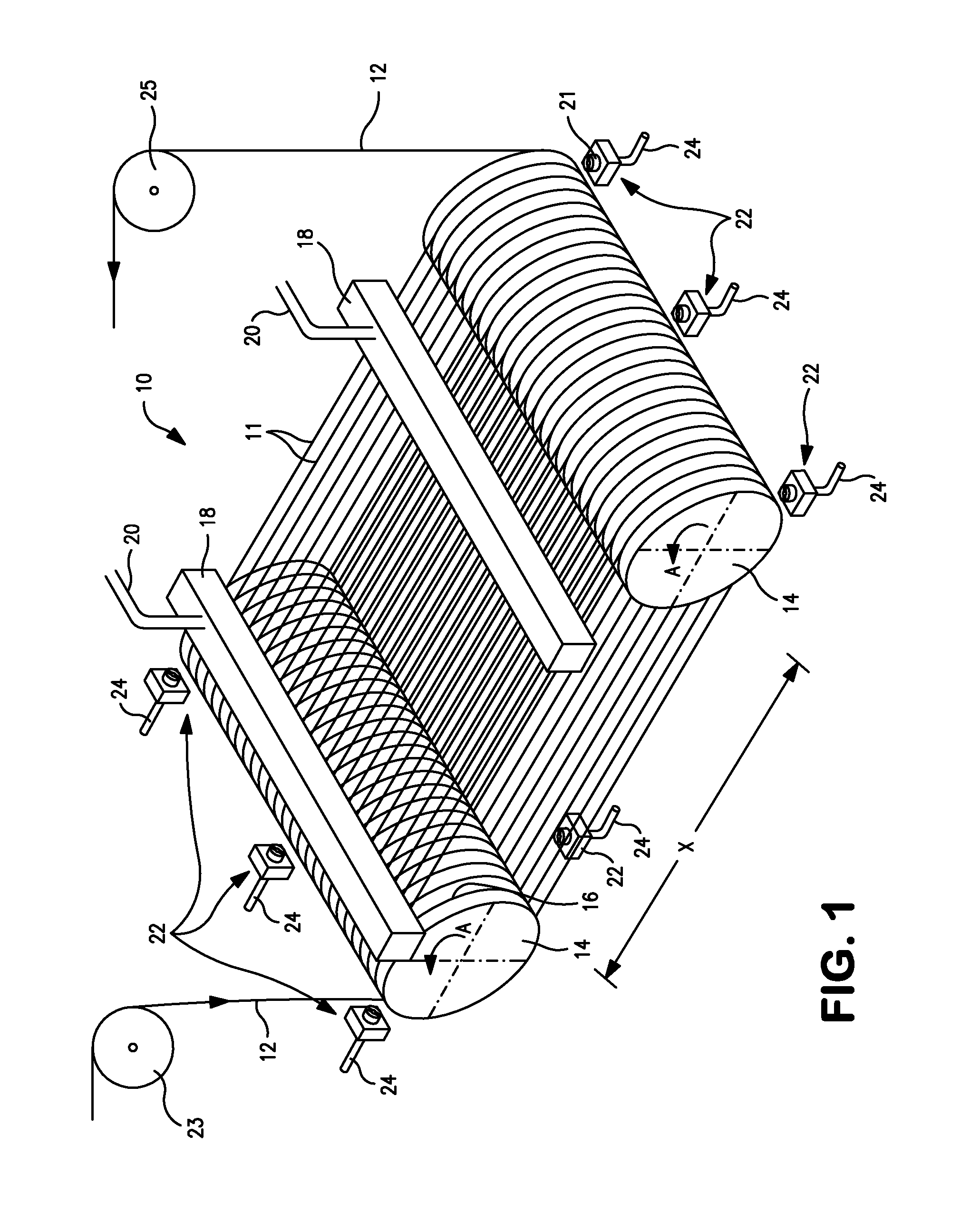
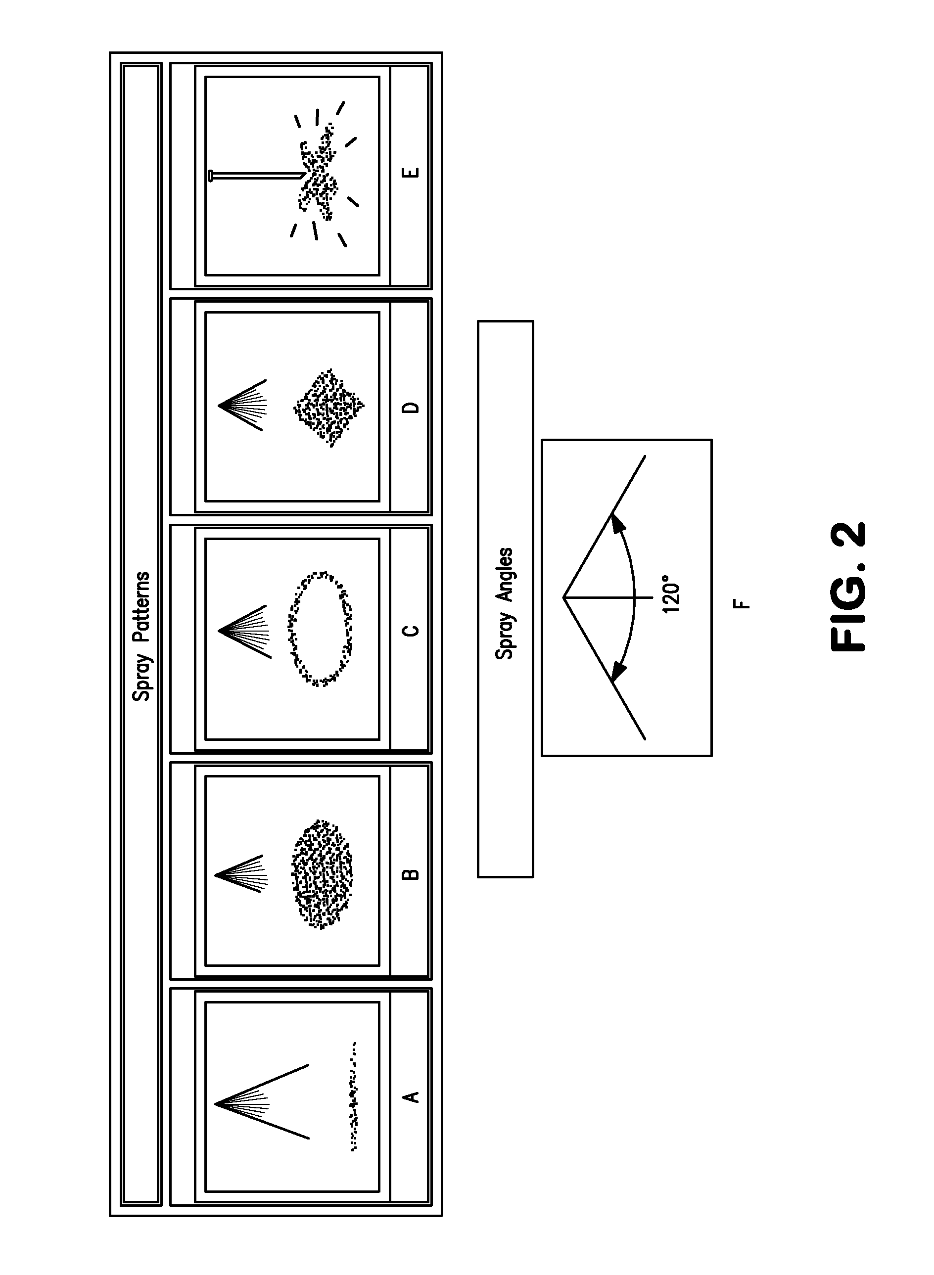
[0007]In a preferred aspect, the wiresaw apparatus of the present invention includes at least one cleaning fluid dispenser adapted to apply an aqueous cleaning fluid onto at least one of the movable or rotatable wiresaw components. The wiresaw components that the cleaning fluid dispenser is adapted to apply cleaning fluid to include, for example, a cutting wire, a wire guide groove, a wire guide roller, and / or a pulley for directing the wire into or out of the cutting region. The cleaning fluid dispenser dispenses fluid preferably at a pressure in the range of 10 to 160 pounds-per-square inch. The cleaning fluid dispenser can dispense fluid before, during or after cutting the substrate. Preferably, the cleaning fluid is applied while the cutting wire is moving. The cleaning fluid dispenser preferably is located from 1 millimeter to 200 millimeters from a cutting wire. In some preferred embodiments, it is desirable to spray cleaning fluid onto a cutting wire as it exits the cutting region and the rollers, i.e., before being wound onto its take-up spool. The cleaning fluid dispenser can include a nozzle adapted to spray the fluid at an angle of 10 degrees to 150 degrees, and can dispense the aqueous cleaning fluid in a linear, circular, ring-shaped, or square dispersion pattern or a solid stream. The cleaning fluid is preferably dispensed with a gas (e.g. air) to create a mist or to increase the impact of the cleaning fluid
[0009]In another preferred aspect, the apparatus includes at least one fluid atomizing or nebulizing nozzle adapted to discharge a mist of an aqueous fluid within the cutting chamber. The mist aids in maintaining a suitable humidity level within the cutting chamber and optionally can help maintain the moisture level of the cutting fluid slurry and / or help prevent encrustation of the wiresaw components with dried cutting fluid. The at least one fluid atomizing or nebulizing nozzle is adapted to dispense the aqueous fluid at a rate preferably in the range of 2 liters an hour to 20 liters an hour.
[0014]The amount of aqueous cleaning fluid that is discharged from the cleaning fluid dispenser preferably is monitored so as to maintain a suitable level of moisture within the cutting region of the apparatus and to prevent undesirable encrustation of movable and rotatable components or the apparatus by dried cutting slurry.

Problems solved by technology

The cutting slurry can clog or jam the various pulleys and wire guides, causing the performance of the wiresaw to decline.
The cutting slurry deposited on the wiresaw also can lose moisture and create hard deposits on the wiresaw components.
These hard deposits increase the frequency of wire breakage and other wiresaw malfunctions during the wiresaw cutting process.

Method used


Image

  • Self-cleaning wiresaw apparatus and method
  • Self-cleaning wiresaw apparatus and method
  • Self-cleaning wiresaw apparatus and method

Examples


Embodiment Construction

[0025]The invention disclosed herein is susceptible of embodiments in many different forms. Shown in the drawings and described herein in detail are preferred embodiments of the invention. It is to be understood, however, that the present disclosure is an exemplification of the principles of the invention and does not limit the invention to the illustrated embodiments.

[0026]A preferred embodiment of a self-cleaning wiresaw cutting apparatus of the present invention is shown in FIG. 1. Wiresaw apparatus 10 is adapted to apply an aqueous cleaning fluid to portions of the wiresaw as a spray or mist before, after, and / or during operation of the wiresaw. Wiresaw apparatus 10 includes cutting wire 12 disposed in multiple cutting loops 11 over first and second rollers 14. Wire guide grooves 16 are located on the surface of rollers 14 to maintain a constant spacing or pitch between loops 11. Rollers 14 are separated from one another by distance X, which is determined by the desired length o...


PUM

PropertyMeasurementUnit
tensionaaaaaaaaaa
distanceaaaaaaaaaa
spray angleaaaaaaaaaa

Abstract

The present invention provides a self-cleaning wiresaw cutting apparatus including a cleaning mechanism adapted to clean the components of the wiresaw before, during, or after a cutting process or to humidify the cutting region of the apparatus. The apparatus contains at least one dispenser adapted to dispense an aqueous fluid onto various components of the wiresaw.

Description

FIELD OF THE INVENTION[0001]This invention relates to a self-cleaning wiresaw apparatus. In particular this invention relates to an apparatus having a dispenser nozzle adapted to clean the components of a wiresaw and methods of cleaning wiresaw components.BACKGROUND OF THE INVENTION[0002]Wiresaw cutting is the dominant method for slicing ingots into thin wafers for use in the integrated circuits and photo-voltaic device (PV) industries. This method is also commonly used for wafering substrates of other materials, such as sapphire, silicon carbide, or ceramic substrates. A wiresaw typically includes one or more spools of fine wire deployed web-like array of wire loops, or a wireweb, where the individual wires have a diameter around 0.1 mm and are arranged in parallel loops, at a loop-to-loop distance of 0.1 to 1.0 mm, by threading the wire through a series of spools, pulleys and wire guides. Slicing or cutting of a workpiece (e.g., a silicon ingot), is accomplished by contacting the ...

Claims


Application Information

Patent Timeline
Patent Type & Authority Applications(United States)
IPC IPC(8): B28D7/02B28D5/00B28D1/08
CPCB28D5/0076Y10T83/242
Inventor GRUMBINE, STEVENBARROS, CARLONAGARAJAN, RAMASUBRAMANYAM
Owner CABOT MICROELECTRONICS CORP
Learn More