Polarization interference imaging spectrum system

An interference imaging and spectroscopy system technology, applied in the field of polarization interference imaging spectroscopy system, can solve the problem of not obtaining spatial information, and achieve the effects of convenient image processing, reducing stray light, and overcoming the insufficient size of the CCD.

Inactive Publication Date: 2010-09-01
BEIJING JIAOTONG UNIV
View PDF0 Cites 14 Cited by
  • Summary
  • Abstract
  • Description
  • Claims
  • Application Information

AI Technical Summary

Problems solved by technology

But this method can only provide the spectral information o

Method used


Image

  • Polarization interference imaging spectrum system
  • Polarization interference imaging spectrum system
  • Polarization interference imaging spectrum system

Examples


Embodiment Construction

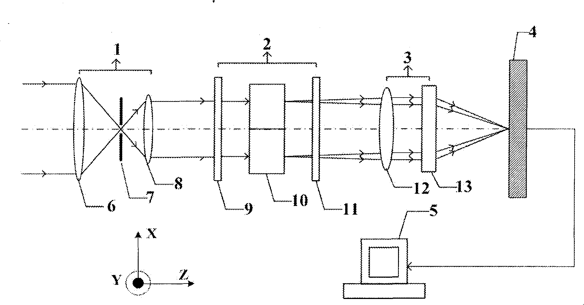
[0029] See attached figure 1 , a novel polarization interference imaging spectroscopy system includes a pre-optical system 1 , a polarization interferometer 2 , an imaging system 3 , a CCD detector 4 and a connected computer signal processing system 5 .

[0030] The front optical system 1 includes a lens 6, an incident slit 7, and a collimating lens 8, and its function is to collect, expand and collimate the radiation emitted by the target.

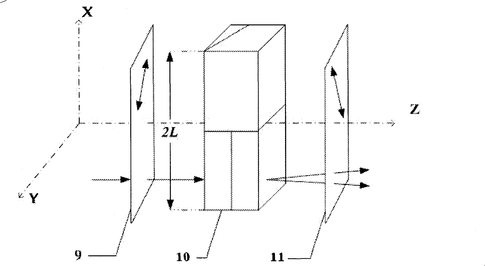
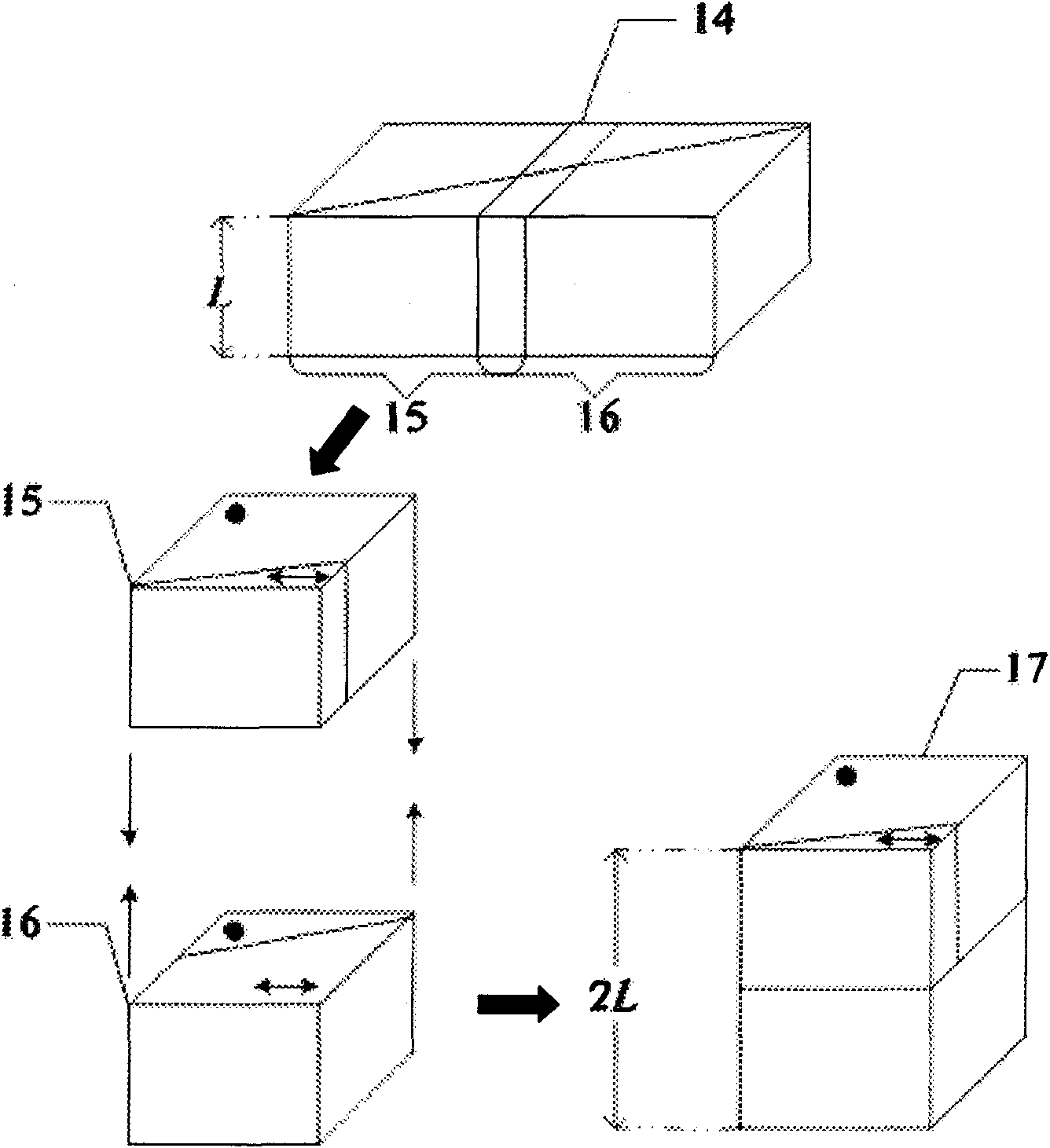
[0031] as attached image 3 As shown, the polarization interferometer 2 includes a polarizer 9, a multilayer Wollaston prism group 10, and an analyzer 11, and the multilayer Wollaston prism group 10 is cut into two pieces by a long Wollaston prism 14 The sub-prism 15 and the sub-prism 16 with the same wedge angle and the same geometric size are stacked up and down; the polarization direction of the polarizer 9 is 45° to the optical axis, and the polarization direction of the analyzer 11 is 45° to the optical axis. ° (90° to the polariza...


PUM


Abstract

The invention discloses a novel polarization interference imaging spectrum system. The multilayer wollaston prism sets are formed by cutting a single wollaston prism set, thereby improving the spectral resolution; an interference image is folded on the different rows on a CCD detector to be collected, thereby overcoming the problem that the CCD can not receive enough size under some conditions; and a slit is used for leading the late image process to be more convenient and simpler, and reducing the stray light.

Description

technical field [0001] The invention belongs to the technical field of optical imaging spectrum systems, and in particular relates to a novel polarization interference imaging spectrum system based on a multilayer Wollaston prism group. Background technique [0002] Interferometric imaging spectroscopy technology based on birefringent crystals as spectroscopic elements is also called polarization interferometric imaging spectroscopy technology. Compared with other imaging spectroscopy techniques, it has two most prominent advantages: one is that it guarantees The large luminous flux solves the contradiction between high resolution and large luminous flux that cannot be overcome by the dispersion-type imaging spectroscopy technology; the second is a common optical path, which has strong anti-interference and vibration capabilities. [0003] In the polarization interference imaging spectroscopy technology based on birefringent crystals as spectroscopic elements, Savart polariz...

Claims


Application Information

Patent Timeline
IPC IPC(8): G01J3/45G02B5/04
Inventor 高瞻陈筱磊林泽鸣冯其波
Owner BEIJING JIAOTONG UNIV
Why Eureka
Try Eureka