Solder resist coating for rigid-flex circuit board

A rigid-flex bonding, solder resist technology, applied in the direction of circuit bendable/stretchable parts, printed circuits, printed circuits, etc., can solve the problems of wasting time, high cost, avoid peeling, prolong life, life improved effect

Active Publication Date: 2010-09-01
VTESCO TECH GMBH
View PDF12 Cites 10 Cited by
  • Summary
  • Abstract
  • Description
  • Claims
  • Application Information

AI Technical Summary

Problems solved by technology

This in turn is time consuming and at the same time costly

Method used


Image

  • Solder resist coating for rigid-flex circuit board
  • Solder resist coating for rigid-flex circuit board
  • Solder resist coating for rigid-flex circuit board

Examples


Embodiment Construction

[0032] In the description of the embodiments of the invention, the terms "upper", "lower", and the underside and upper side of the circuit board are used as reflected in the figures. It is however clear to those skilled in the art that such terms may be used interchangeably where possible.

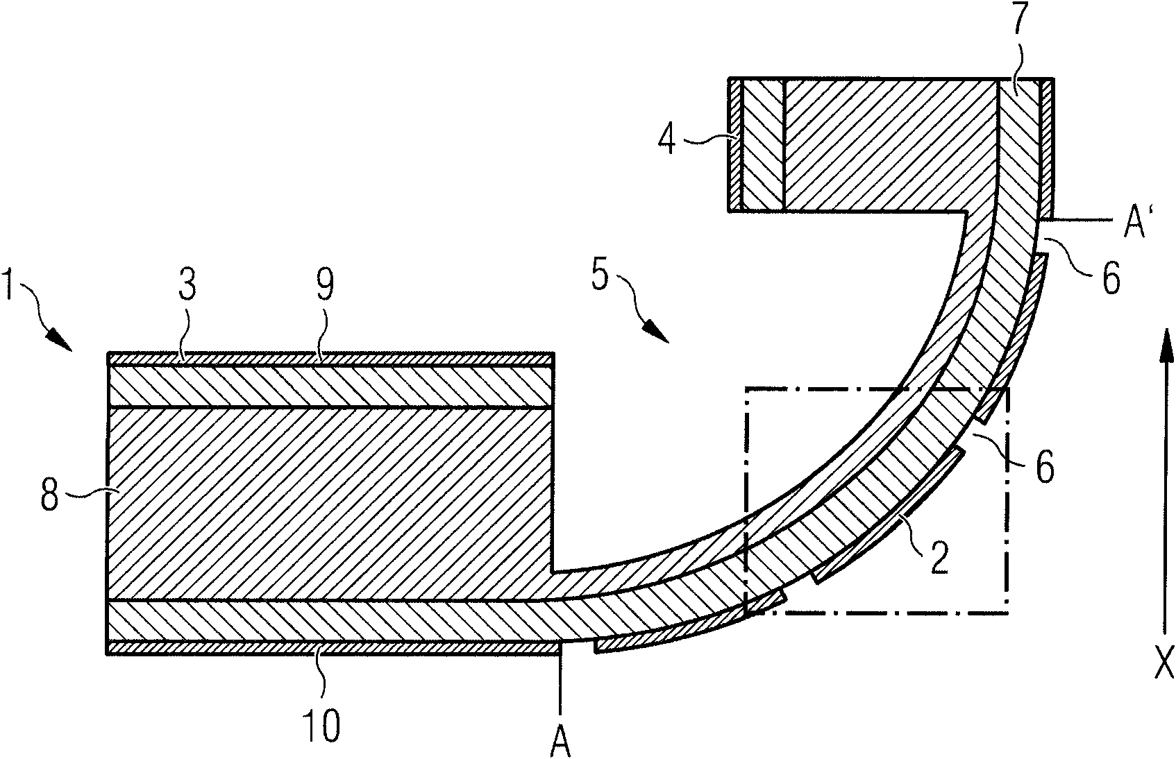
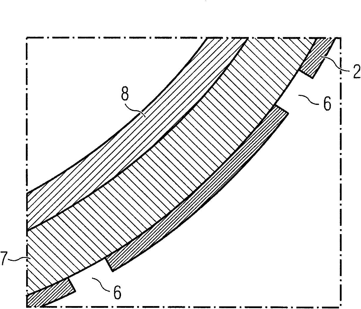
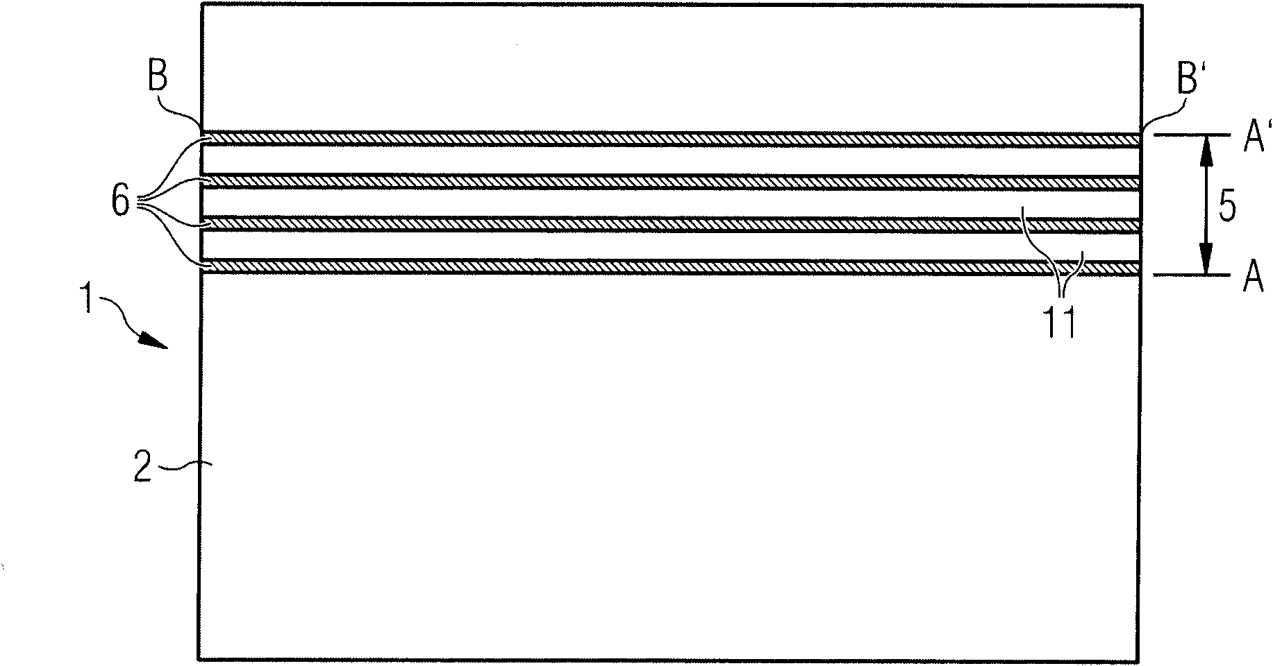
[0033] figure 1 A cross-sectional view of a rigid-flex circuit board 1 with a solder resist varnish layer 2 according to the invention is shown. The rigid-flex circuit board 1 has a first rigid area 3 and a second rigid area 4 . Between the rigid regions 3 and 4 is arranged a bending region 5 in which the printed circuit board 1 is designed to be flexible. In the bending region 5 extending over the length A-A', the circuit board 1 can be made of a rigid circuit board material with a small thickness. The bending area 5 can be produced as a recess in the circuit board 1 , for example by deep milling. According to the invention, the solder resist lacquer layer 2 can have one or more expan...


PUM


Abstract

The invention relates to a solder resist coating for a rigid-flex circuit, particularly to a solder resist coating (2) for a rigid-flex circuit board (1), containing one or more conductor tracks (13) and at least one flex area (5). The solder resist coating (2) has one or more movement gaps (6) in the flex area (2) of the circuit board (1). In addition, an electronic module is formed having at least one rigid-flex circuit board (1) with a solder resist coating (2). The invention also discloses a method for manufacturing the solder resist coating (2).

Description

technical field [0001] The invention relates to a solder resist varnish for rigid and in some areas flexible printed circuit boards. Background technique [0002] Circuit boards generally have to be adapted in terms of their shape and arrangement to the structural and external boundary conditions. In motor vehicle technology, aspects such as safety, cost and weight savings, and aesthetics can take precedence over the mounting size and shape of the circuit board. [0003] For this purpose, circuit boards with printed circuits, with rigid and flexible subregions for electronic regulation and control, have been used in recent years in instruments or vehicles. The freedom of possible three-dimensional shape of the printed circuit board can be increased by the flexible partial region. For cost reasons, circuits are currently mainly produced using rigid circuit board materials, wherein the circuit board material has a smaller thickness in the flexible regions than in the rigid r...

Claims


Application Information

Patent Timeline
Patent Type & Authority Applications(China)
IPC IPC(8): H05H1/00H05K3/28
CPCH05K1/028H05K3/3452H05K3/4691H05K2201/0989H05K1/0278H05K2201/09909Y10T29/49124Y10T29/49126Y10T29/49128Y10T29/49144Y10T428/24273
Inventor D·巴冈格M·德克G·德鲁T·里普尔B·罗勒
Owner VTESCO TECH GMBH
Why Eureka
Try Eureka