Unlock instant, AI-driven research and patent intelligence for your innovation.

Thin-film fixed bed reactor for the chemical treatment of a finely divided catalytic solid

一种固定床反应器、反应器的技术,应用在催化剂活化/制备、化学仪器和方法、化学/物理过程等方向,能够解决流化床反应器良好分布困难等问题

Active Publication Date: 2010-09-01
INST FR DU PETROLE +1
View PDF2 Cites 3 Cited by
  • Summary
  • Abstract
  • Description
  • Claims
  • Application Information

AI Technical Summary

Problems solved by technology

[0020] Finally, fluidized bed reactors may in some cases have difficulties with good gas distribution unless a distribution system is used that causes a large pressure drop

Method used


Image

  • Thin-film fixed bed reactor for the chemical treatment of a finely divided catalytic solid
  • Thin-film fixed bed reactor for the chemical treatment of a finely divided catalytic solid
  • Thin-film fixed bed reactor for the chemical treatment of a finely divided catalytic solid

Examples


Embodiment Construction

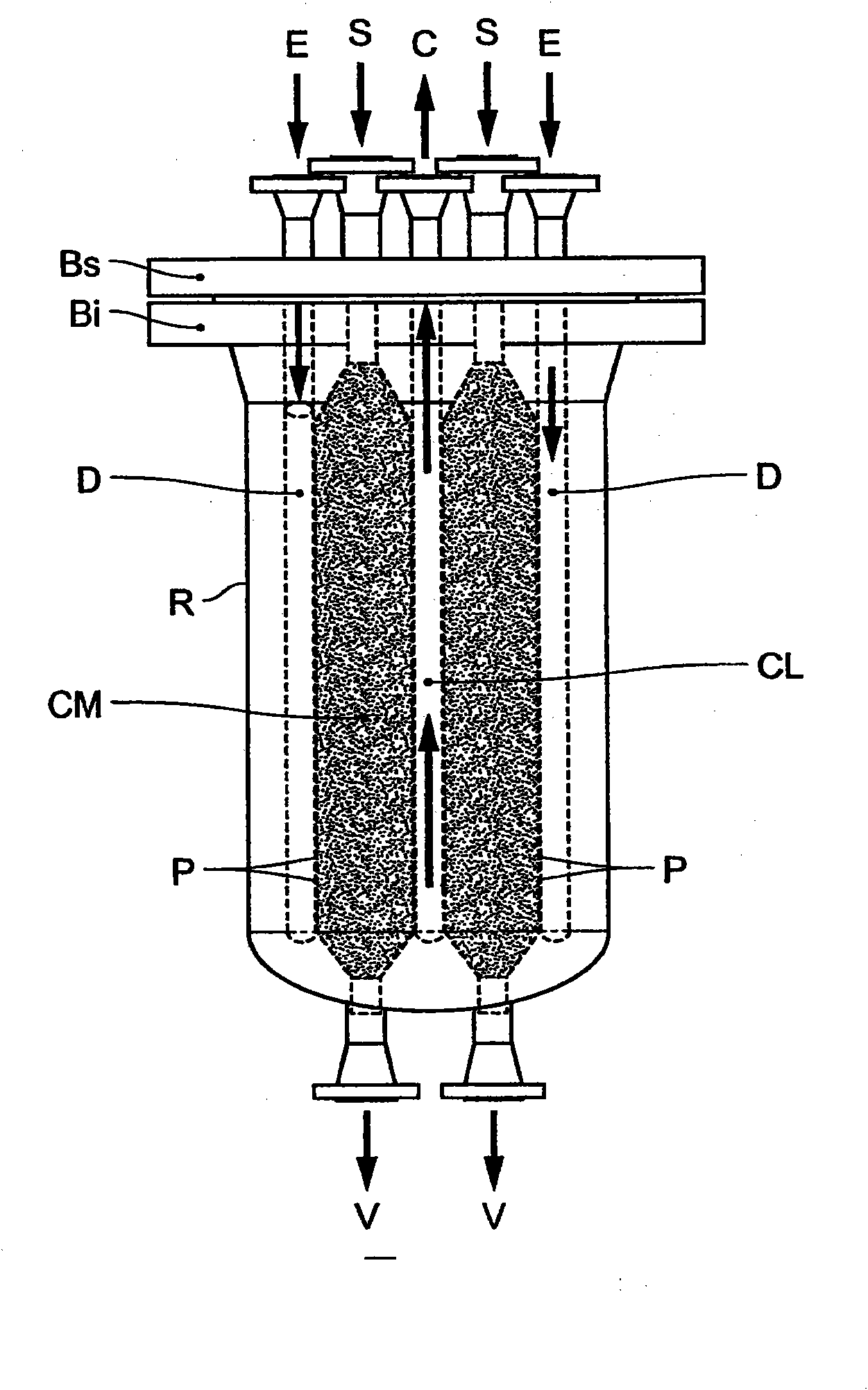
[0092] The following reference corresponds to the planar structure Figure 2a , 2b , 2c for description.

[0093] The invention comprises a fixed-bed reactor with thin layers consisting of modules M-like assemblies operating in parallel and enclosed in a common vessel constituting the envelope R of said reactor.

[0094] In this particular case, the modules are identical.

[0095] The reactor is used to treat catalyst solids in the reactor in the form of fine particles typically in the range of 30 to 100 microns in diameter.

[0096] Said treatment, commonly referred to by those skilled in the art as "reduction", uses a reactive gas, which is hydrogen, optionally diluted with an inert gas (typically nitrogen) at any dilution, but preferably between 25 % to 35% (volume). Each module M of the reactor consists of components comprising the following elements:

[0097] a collector CL for reaction effluents, adjacent to the porous outlet face of said enclosure P;

[0098] The ...


PUM


Abstract

The present invention describes a thin-film fixed bed reactor intended for chemical treatments, especially for the reduction of the Fischer-Tropsch synthesis catalyst. The reactor is designed in the form of similar compact modules, and observes a ratio of linear pressure loss to outlet pressure between certain limits.

Description

technical field [0001] The present invention relates to thin layer fixed bed reactors for carrying out oxidation or reduction chemical reactions of ground solids (extrudates, beads or powders) which are used as catalysts or catalyst precursors in refining or petrochemical processes. [0002] More specifically, the present invention is applicable to the reduction with hydrogen of cobalt-based Fischer-Tropsch synthesis catalysts for use in the liquid phase. [0003] Fischer-Tropsch synthesis catalysts typically consist of fine solid particles with diameters in the range of 30 to 100 microns (abbreviated as μm elsewhere herein). [0004] The catalyst is usually in the form of its oxide after synthesis (Co 3 o 4 ). Therefore, the reduction step should be performed before using the catalyst in the Fischer-Tropsch synthesis reactor. [0005] This reduction step is carried out using a reducing gas, which is pure hydrogen or hydrogen diluted in an inert gas. [0006] The present ...

Claims


Application Information

Patent Timeline
Patent Type & Authority Applications(China)
IPC IPC(8): B01J8/00B01J8/02B01J8/12B01J37/18F26B17/12B01J35/00
CPCB01J2219/185C10G2/32B01J8/065B01J35/023B01J8/02B01J2219/00031B01J8/12B01J2208/022C10G2300/703B01J23/75B01J8/009B01J8/0207B01J2219/1923B01J37/18C10G2/34B01J35/40B01J8/0214B01J2208/021B01J8/0278
Inventor D·多齐克G·考塞E·卡普拉尼J·-C·维吉J·-M·施韦特泽A·福雷特
Owner INST FR DU PETROLE
Features
  • R&D
  • Intellectual Property
  • Life Sciences
  • Materials
  • Tech Scout
  • Unparalleled Data Quality
  • Higher Quality Content
  • 60% Fewer Hallucinations
Learn More