
Protection system for subsea seawater injection pumps

A pump system and pump cavity technology, applied in the field of pump systems, can solve problems such as pollution

Inactive Publication Date: 2010-09-01
AKER SUBSEA AS
View PDF3 Cites 3 Cited by
  • Summary
  • Abstract
  • Description
  • Claims
  • Application Information

AI Technical Summary

Problems solved by technology

[0005] Also, the flow through the pump will be contaminated by fluid leaking from the motor through the shaft seal system, which presents a problem with the need to clean the pumped fluid or reduce leakage due to the restriction of leakage into the environment

Method used


Image

  • Protection system for subsea seawater injection pumps
  • Protection system for subsea seawater injection pumps
  • Protection system for subsea seawater injection pumps

Examples


Embodiment Construction

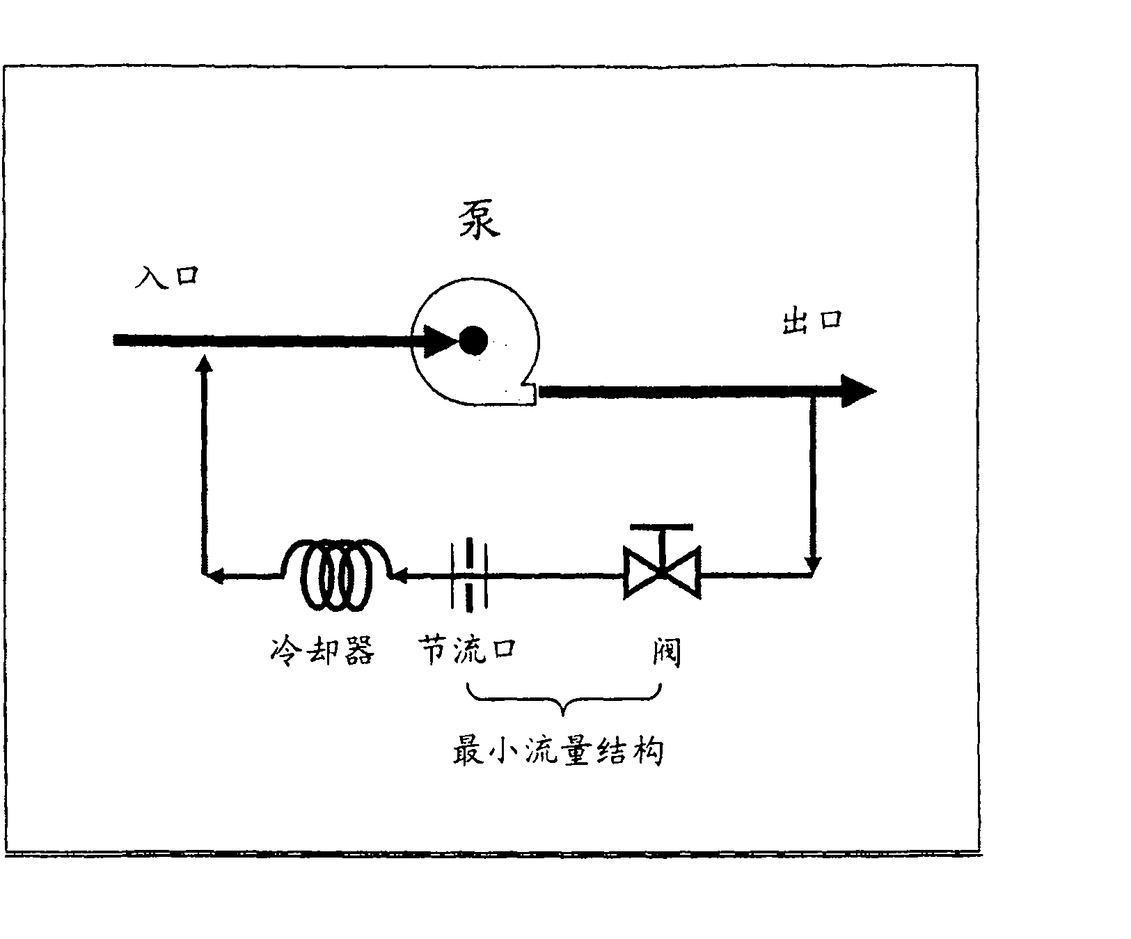
[0011] Current subsea pumping systems employ conventional electric motors having windings with connections that are not fully insulated from the environment and that are filled with dielectric oil that acts as an additional insulator. According to environmental regulations, the discharge of this dielectric oil into the environment is not permitted. For systems utilizing such fluids, such as figure 1 shown, a closed minimum flow loop must be used to protect the pump.

[0012] In a closed cycle, where the same water is circulated, the energy applied to the water by the pump will cause the fluid and thus the pump to overheat and eventually cause damage. Therefore, closed cycle solutions require orifices / chokes, piping and valves to form a closed cycle, and coolers to avoid overheating of the recirculating fluid within the closed cycle.

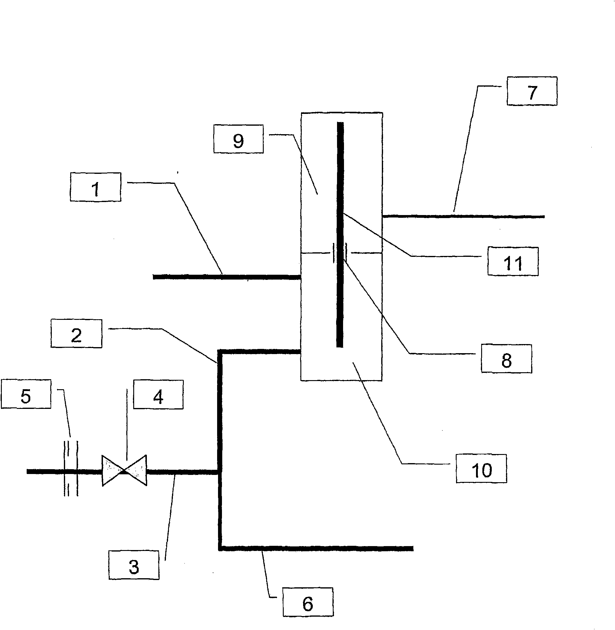
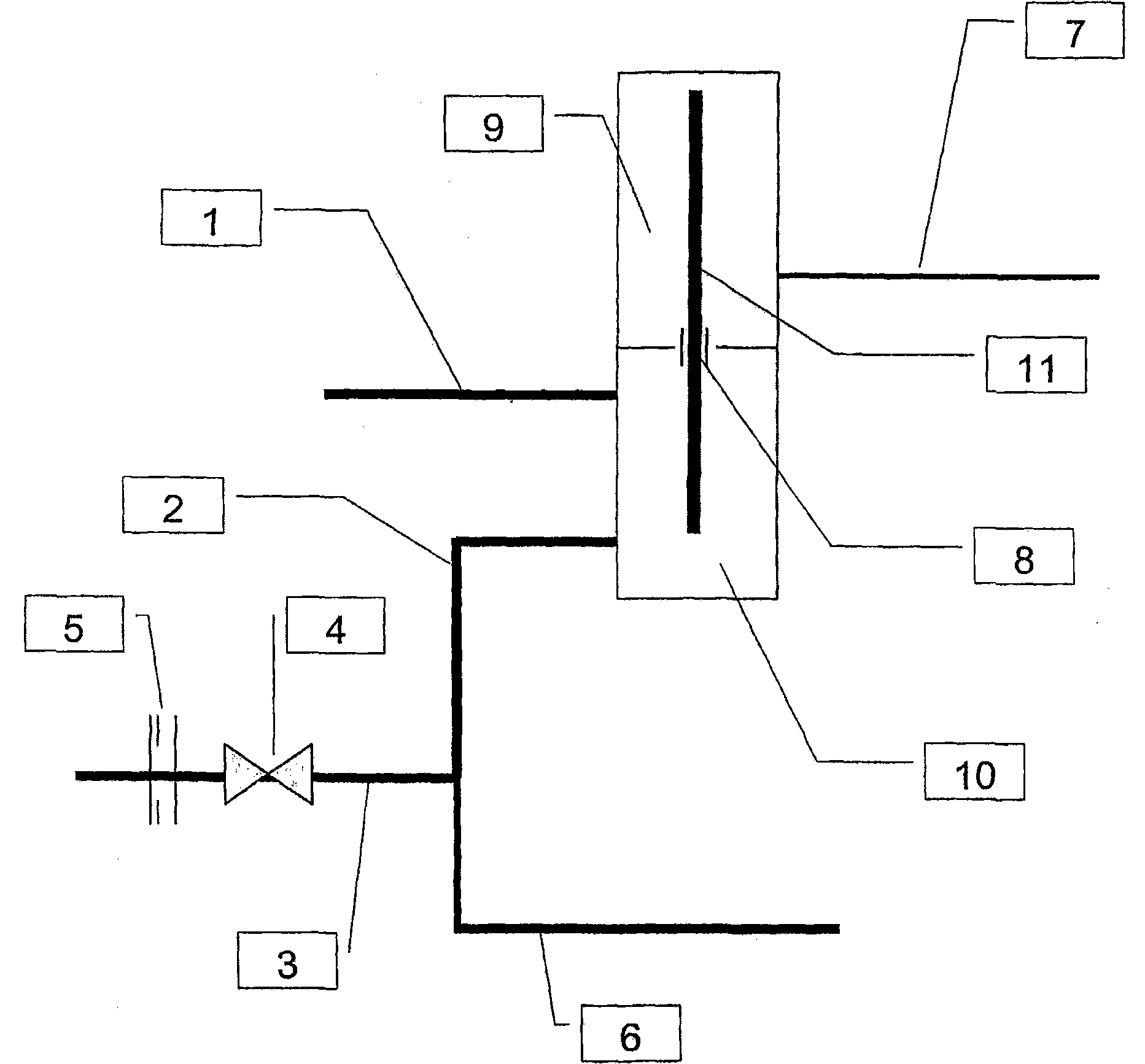
[0013] The present invention, as will be explained below, will significantly reduce the size and number of components required, ultimately res...


PUM


Abstract

This invention relates to a pump system, especially for boosting the flow rate of a fluid through a pipe (1, 2, 6), comprising a pump positioned in a pump chamber (10) for pumping at a chosen rate, and a motor driving said pump, the motor being positioned in a chamber (9) being provided with a pressurized fluid, the pressure of which being higher than the pressure in the pump chamber, the motor and the pump chambers being separated by a seal (8), the seal allowing a leakage of said pressurized fluid between them, wherein the pressurized fluid is acceptable to the pump environment and the system comprises a discharge branch line (3) coupled to the pipe(6) and positioned downstream from said pump, the discharge branch line having an outlet into the environment.

Description

technical field [0001] The invention relates to a pump system. Background technique [0002] Pumps usually have to be operated above a minimum flow to avoid unstable behavior, overheating and consequent pump damage. To achieve this protection of the pump under minimum flow requirements, a minimum flow structure is included. Such structures typically include a flow path from the outlet back to the inlet through a restriction. This bypass can be continuously triggered or achieved by a valve that is triggered by a small flow or high pressure at the outlet. Centrifugal pumps for subsea raw seawater can have the same type of minimum flow configuration as commonly used on-road pumps. [0003] Subsea pumping systems are designed to move fluids, ie liquids and / or gases, from one place to another. This can be achieved by using a pump. Common to all processes involved in moving fluids is the need for external energy. This energy is usually added by using some type of motor and f...

Claims


Application Information

Patent Timeline
IPC IPC(8): F04D13/08F04D29/10
CPCF04D29/108F04D13/086Y10T137/86035F04D13/08F04D29/10
Inventor 奥顿·格里宁斯坦·V·拉森盖尔·I·奥尔森
Owner AKER SUBSEA AS
Features
  • Generate Ideas
  • Intellectual Property
  • Life Sciences
  • Materials
  • Tech Scout
  • Unparalleled Data Quality
  • Higher Quality Content
  • 60% Fewer Hallucinations
Learn More