Electrical internal combustion engine actuating arrangement

A technology for regulating devices and internal combustion engines, applied in electromechanical devices, valve operation/release devices, valve devices, etc., can solve the problems of no longer guaranteeing the clamping of the plug-in tongue, easy to cause vibration, etc., and achieve high installation reliability. , the effect of high positioning accuracy

Active Publication Date: 2010-09-08
PIERBURG GMBH & CO KG NEUSS
View PDF1 Cites 2 Cited by
  • Summary
  • Abstract
  • Description
  • Claims
  • Application Information

AI Technical Summary

Problems solved by technology

This can lead to the fact that the clamping of the plug tongues in the sockets is no longer guaranteed, or that the contacting takes place only on one side and thus causes vibrations in particular

Method used


Image

  • Electrical internal combustion engine actuating arrangement
  • Electrical internal combustion engine actuating arrangement
  • Electrical internal combustion engine actuating arrangement

Examples


Embodiment Construction

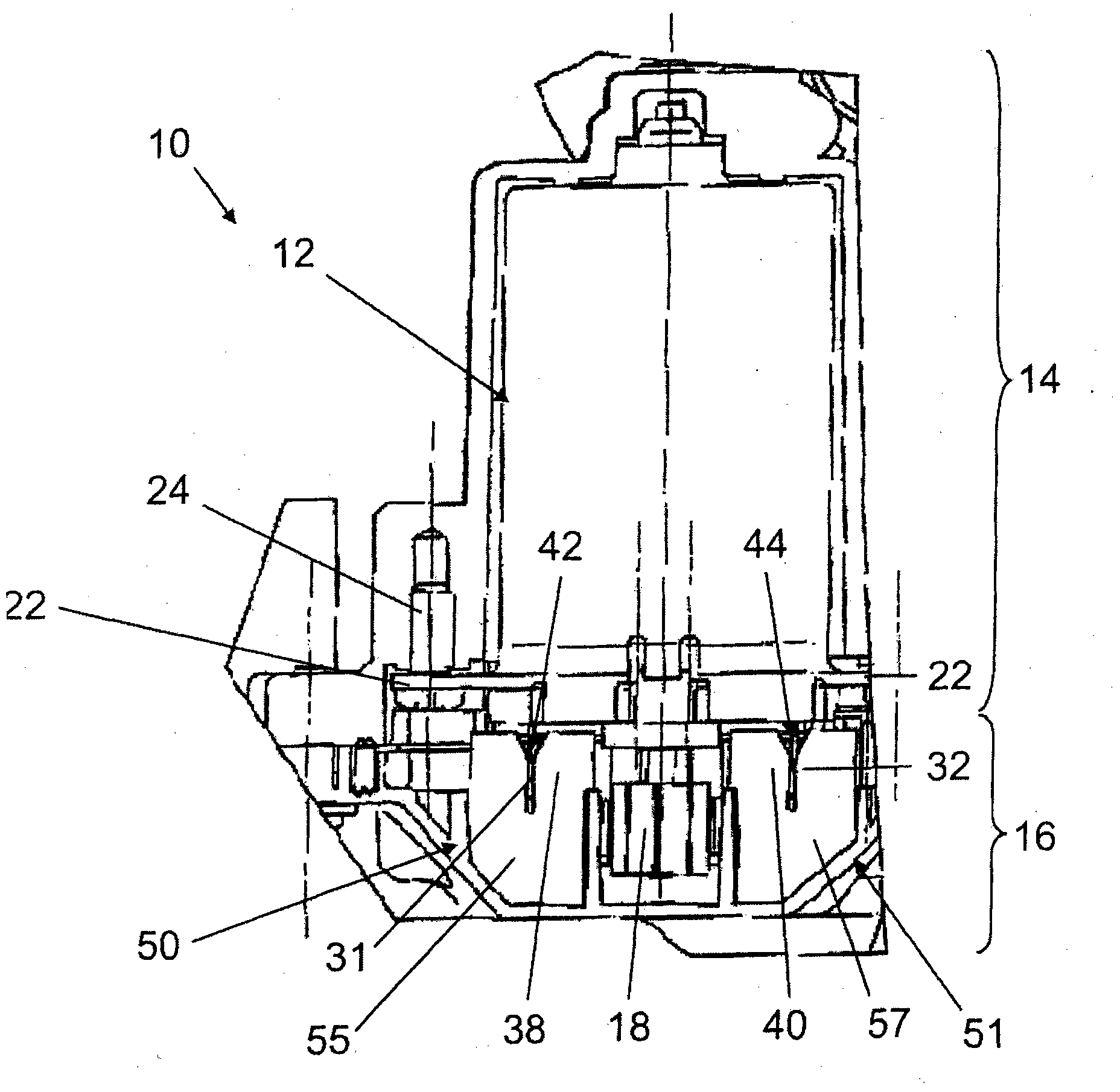
[0034] exist figure 1 A longitudinal sectional view of the entire electrical control device 10 of an internal combustion engine is shown in . The regulating device 10 is used, for example, to regulate a regulating mechanism of an internal combustion engine, for example to regulate a throttle valve, a directional valve, a screw valve or a switching valve. exist Image 6 An adjusting mechanism arrangement 90 with a throttle valve as adjusting mechanism 92 is shown in FIG. The adjusting mechanism 92 can be arranged directly on the output shaft of the electric motor 12 , but it can also be driven, as before, indirectly via the transmission 26 with the output shaft 80 .

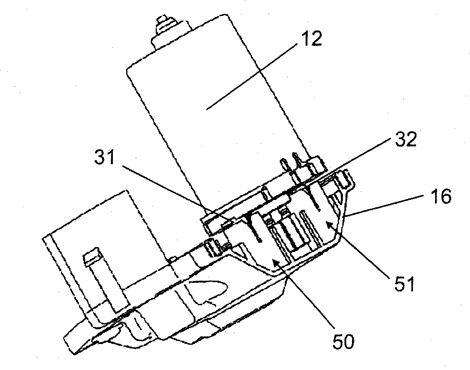
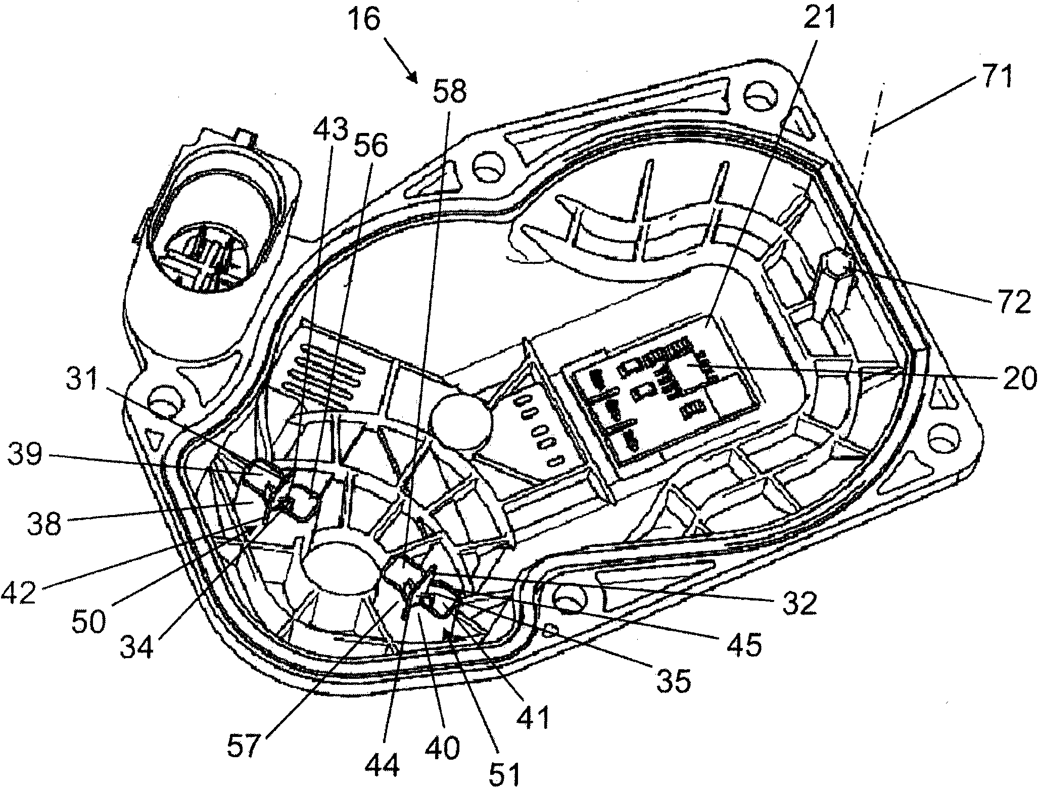
[0035]The adjusting device 10 has a gas-tight and liquid-tight housing consisting of a composite aluminum housing 14 and a plastic housing cover 16 which closes the open side of the housing 14 . The drive motor 12 with a driven pinion 18 is accommodated in the housing 14 . The output pinion 18 drives a housing...


PUM


Abstract

The invention relates to an electrical internal combustion engine actuating arrangement for adjusting actuating elements of an internal combustion engine. The housing body (14) contains a drive motor (12) and is closed off by a housing cover (16). The actuating arrangement has, at the housing cover side, a position sensor (20) which interacts with a position transducer (82) of the housing-body-side drive output shaft (80). The housing cover (16) and the drive motor (14) are electrically connected to one another by means of at least one electrical plug connection arrangement (50, 51). The housing cover (16) and the housing (14) have a positioning arrangement (70) which is composed of a positioning pin (72) and a positioning bore (74). The plug connection arrangement is formed in each case by a plug blade (31, 32) and an opposing plug clamp (34, 35) having a plug-in slot (36, 37). The plug arrangement (50, 51) has, at the plug clamp side, in each case at least one separate plug blade guide (38, 39, 40, 41) with a guide slot (42 to 45) which is arranged in each case parallel to the associated plug-in slot (36, 37) of the respective plug blade (31, 32). It is the object of the invention to create an actuating arrangement whose position sensor is positioned precisely during assembly and which ensures good contact between the drive motor and the housing cover.

Description

technical field [0001] The invention relates to an electrical control device for an internal combustion engine with a housing holding a drive motor and a driven shaft with a position sensor, and with a housing cover with a position receiver. Background technique [0002] The format-type adjusting device has at least one electrical plug-in device, via which the housing cover and the drive motor are electrically connected to one another. The plug-in device is composed of a plug-in tongue and a plug-in clip opposite to each other and having a slot. [0003] The adjusting device is used in a motor vehicle driven by an internal combustion engine to adjust an adjusting mechanism, such as a throttle valve, a directional valve, a screw valve or a switching valve, wherein the adjusting mechanism is either arranged directly on the drive shaft of the drive motor, Either indirectly via a transmission, via a lever or a connecting rod to the output shaft of the drive motor. [0004] Suc...

Claims


Application Information

Patent Timeline
Patent Type & Authority Applications(China)
IPC IPC(8): F02D11/10F02D9/10F16K31/04H02K5/00
CPCF02D2400/18H02K5/225F02D9/105F02D2011/102F02D2200/0404H02K11/0015H02K2211/03F02D2400/22F02D11/106H02K7/116H02K11/21
Inventor 拉尔夫·内斯托马斯·施罗德
Owner PIERBURG GMBH & CO KG NEUSS
Why Eureka
Try Eureka