Heating friction stir welding method

A technology of friction stir and welding methods, applied in welding equipment, non-electric welding equipment, metal processing equipment, etc., can solve the problems of plastic deformation of materials and insufficient flow, limited frictional heat, and reduced heat input of welded joints, etc., to improve flow The effects of increased resistance and plastic deformation capacity, improved tensile properties, and increased width of the connecting zone

Inactive Publication Date: 2010-09-15
CHONGQING UNIV
View PDF0 Cites 12 Cited by
  • Summary
  • Abstract
  • Description
  • Claims
  • Application Information

AI Technical Summary

Problems solved by technology

However, this process also has difficulties—that is, how to improve the plastic deformation ability of the workpiece to be welded
During the welding process, due to the limited frictional heat generated between the stirring head and the workpiece, the plastic deformation and insufficient flow of the material will cause defects such as pores and incomplete fusion in the weld
Although increasing the rotation speed of the stirring head can increase the welding heat input, as the time increases, the friction between the surface of the welding joint and the workpiece decreases, which will lead to a decrease in the heat input to the welding joint
In addition, reducing the moving speed of the stirring head can also significantly increase the welding heat input, but the low moving speed will lead to a large residual stress in the workpiece after welding, which will seriously reduce the mechanical properties of the welded joint

Method used


Image

  • Heating friction stir welding method
  • Heating friction stir welding method
  • Heating friction stir welding method

Examples


example 1

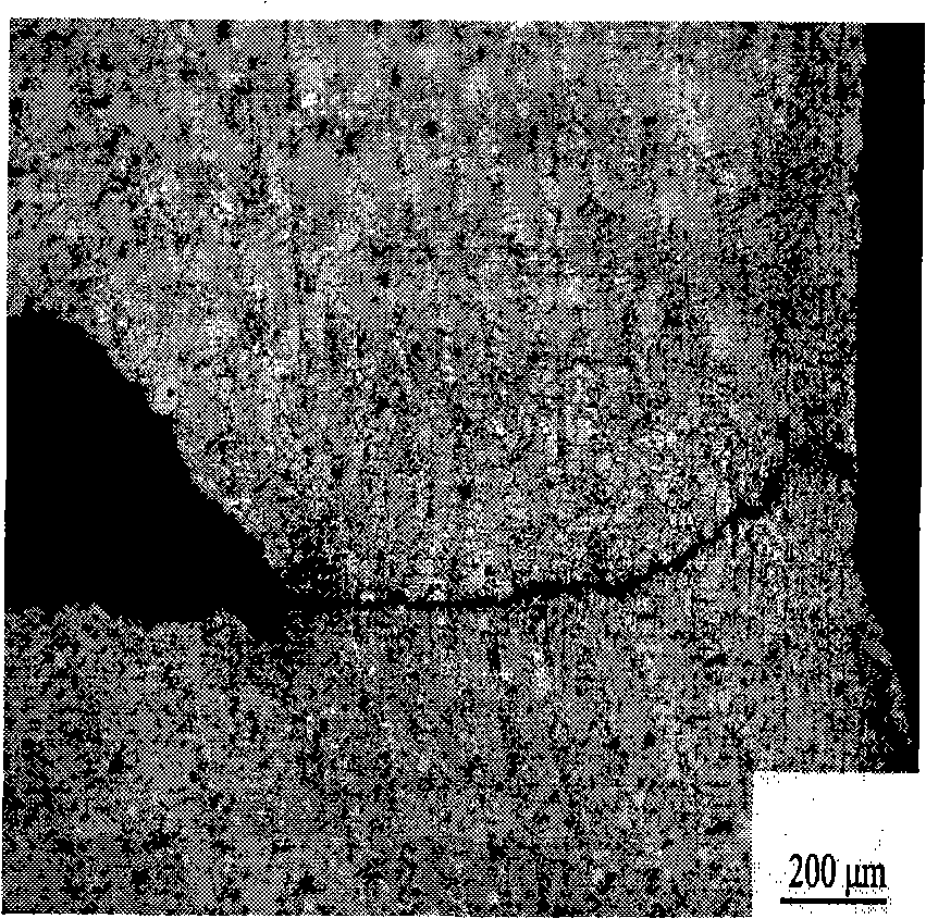
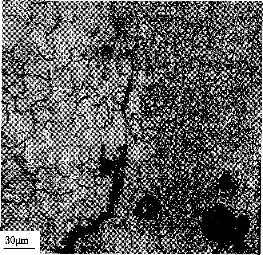
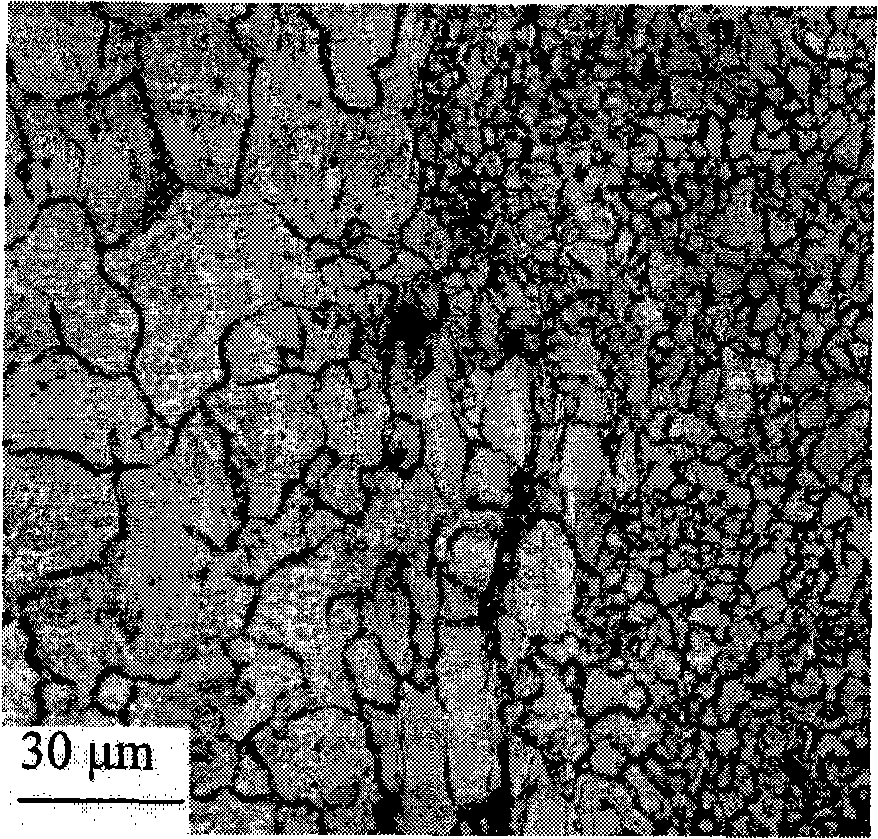
[0018] Before welding, the surface of the 3mm magnesium alloy AZ31 plate is ground and fixed on the clamping device, and then the clamping device is fixed on the temperature-controllable resistance furnace heating equipment. Then adjust the temperature of the resistance furnace to 300° C. and heat until the temperature is stable. During the friction stir welding process, the heating temperature of the resistance heating equipment remains constant until the end of the welding process.

example 2

[0020] Before welding, the surface of the 3mm magnesium alloy AZ31 plate is ground and fixed on the clamping device, and then the clamping device is fixed on the temperature-controllable resistance furnace heating equipment. Then adjust the temperature of the resistance furnace to 350° C. and heat until the temperature is stable. During the friction stir welding process, the heating temperature of the resistance heating equipment remains constant until the end of the welding process.

example 3

[0022] Before welding, the surface of the 3mm magnesium alloy AZ31 plate is ground and fixed on the clamping device, and then the clamping device is fixed on the temperature-controllable resistance furnace heating equipment. Then adjust the temperature of the resistance furnace to 400° C. and heat until the temperature is stable. During the friction stir welding process, the heating temperature of the resistance heating equipment remains constant until the end of the welding process.


PUM


Abstract

The invention discloses a heating friction stir welding method, and belongs to the field of friction stir welding technology. The heating friction stir welding is that in the friction stir welding process, a workpiece is heated continuously by a heating device until the welding is completed. The heating friction stir welding method is characterized by comprising the following steps of: before welding, polishing the workpiece to be welded, fixing the workpiece on a holding device, and then fixing the holding device on a temperature-controllable heating device; and adjusting the temperature of the heating device according to different materials until the temperature is proper, and heating the workpiece until the temperature is stable, wherein in the friction stir welding process, the heating temperature of the heating device maintains unchanged until the welding process is completed. Compared with a welding point not subjected to the heating friction stir welding, a welding point by the welding process has the tensile property improved by 50 percent, and the problem that high-melting point and low-plasticity materials are difficult to be subjected to the friction stir welding is solved.

Description

technical field [0001] The invention relates to a heating and friction welding method, comprising the following process, characterized in that: before welding, the surface of the workpiece to be welded is ground and fixed on a clamping device, and then the clamping device is fixed on a temperature-controllable heating device superior. Then adjust the heating equipment to a suitable temperature according to different materials and heat until the temperature is stable. During the friction stir welding process, the heating temperature of the heating equipment remains constant until the end of the welding process. Background technique [0002] When welding materials with traditional fusion welding (such as laser welding, argon arc welding, electron beam welding and gas shielded welding, etc.), the inevitable welding defects often appear due to the melting and solidification process of the material In the weldment, the mechanical properties of the weldment are seriously reduced...

Claims


Application Information

Patent Timeline
Patent Type & Authority Applications(China)
IPC IPC(8): B23K20/12
Inventor 沈骏闵东
Owner CHONGQING UNIV
Why Eureka
Try Eureka