Quick clamping device

A clamping device and fast technology, applied in the direction of workpiece clamping devices, manufacturing tools, etc., can solve the problems of long auxiliary time, low efficiency, slow clamping action, etc., and achieve fast and convenient stroke adjustment, low precision requirements, and easy processing The effect of manufacture

Inactive Publication Date: 2010-09-15
CITIC DICASTAL
View PDF4 Cites 10 Cited by
  • Summary
  • Abstract
  • Description
  • Claims
  • Application Information

AI Technical Summary

Problems solved by technology

But at the same time, it also has the disadvantages of slow clamping action, long auxiliary time and low efficiency.

Method used


Image

  • Quick clamping device
  • Quick clamping device
  • Quick clamping device

Examples


Embodiment Construction

[0011] The details and working conditions of the specific device proposed according to the present invention will be described in detail below in conjunction with the accompanying drawings.

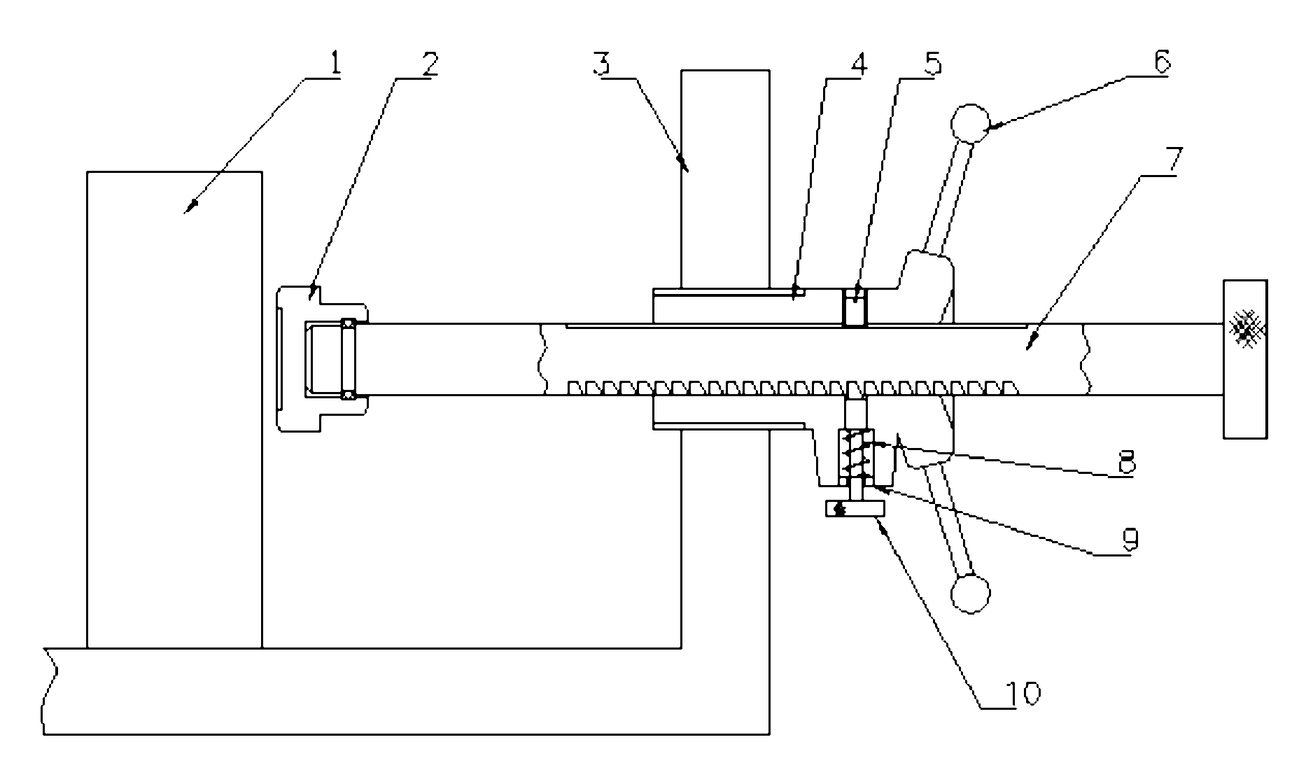
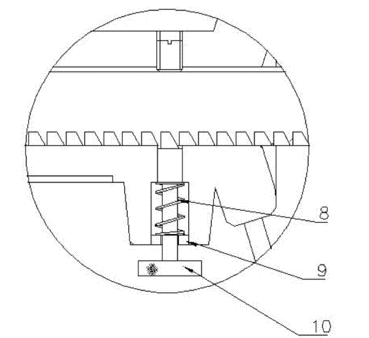
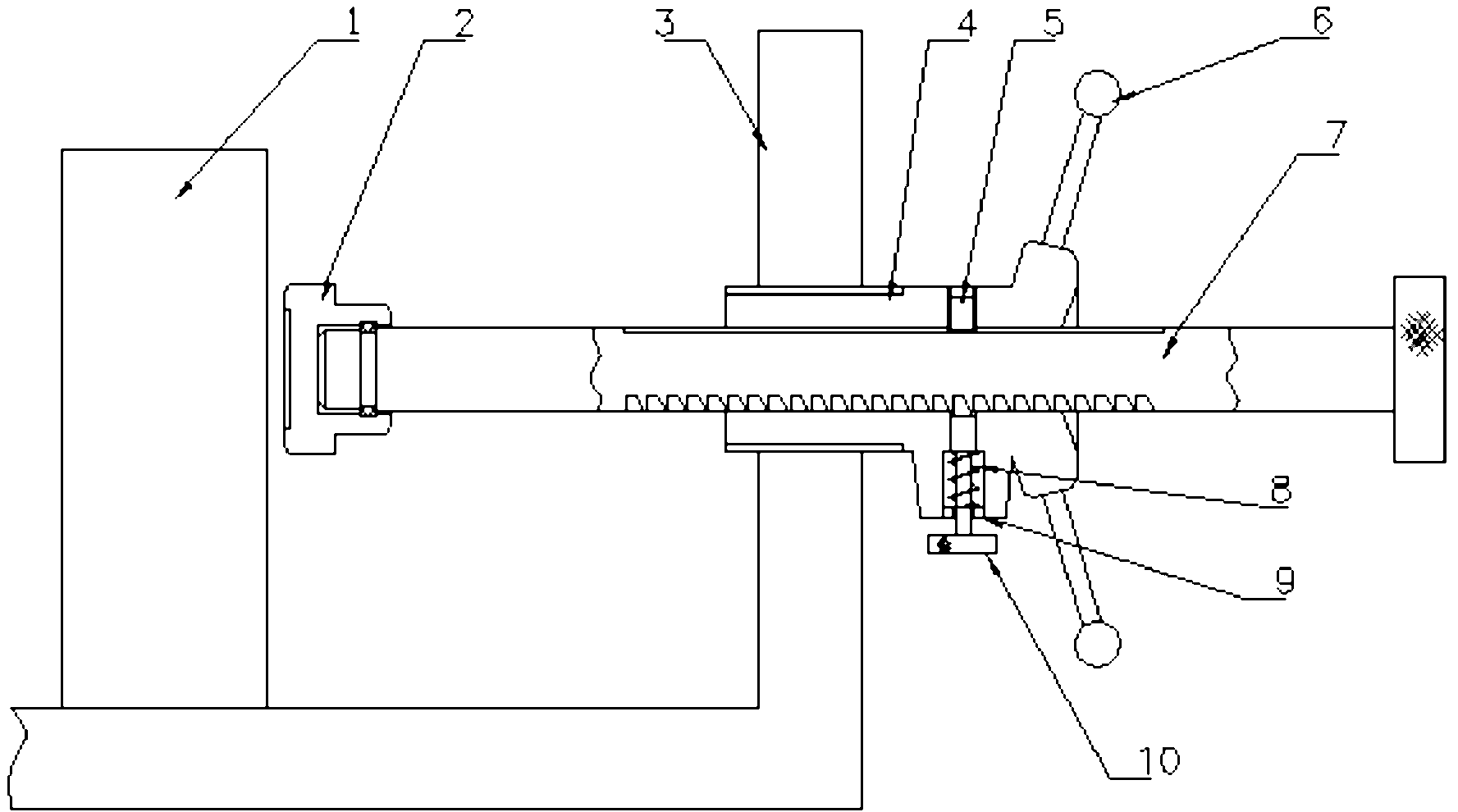
[0012] The technical scheme of the present invention is: whole clamping device structure such as figure 1 Shown: including smooth pressing block 2, clamp body 3, clamping screw 4, anti-rotation pin 5, handle 6, ejector rod 7, spring 8, gland 9, positioning pin 10, clamping screw 4 and clamping body 3 It is threaded connection; for the convenience of rotation, a handle 6 is installed at the right end of the clamping screw 4; gap fit between the ejector rod 7 and the clamping screw 4, so that the clamping screw 4 can slide freely; the anti-rotation pin 5 can prevent the screw from rotating , the other side of the anti-rotation screw on the clamping screw 4 is equipped with a positioning pin 10 to prevent the ejector rod from retreating, and the spring 8 and the gland 9 are arranged between ...


PUM


Abstract

The invention discloses a quick clamping device, which comprises a press block, a clamp body, a clamping screw, an anti-rotating pin, a handle, a mandril, a spring, a gland and a positioning pin, wherein the clamping screw is in threaded connection with the clamp body; the right end of the clamping screw is provided with the handle; the mandril is in clearance fit with the clamping screw; the anti-rotating pin can prevent the rotation of the clamping screw; the other side of an anti-rotating bolt on the clamping screw is provided with the positioning pin for preventing the backward movement of the mandril; and the spring and the gland are arranged between the anti-rotating pin and the positioning pin; and the head of the mandril is provided with the swing smooth-surfaced press block or groove-surfaced press block. The quick clamping device has the advantages of simple structure, low requirements on size and accuracy, quick clamping, convenient and fast travel adjustment, and the like.

Description

technical field [0001] The invention relates to a machining equipment, in particular to a quick clamping device. Background technique [0002] As we all know, the screw clamping mechanism is the most widely used clamping mechanism. It mainly uses threads to directly clamp the workpiece, or forms a composite clamping mechanism with other components or mechanisms to clamp the workpiece. The screw clamping mechanism has the advantages of simple structure, easy manufacture, reliable clamping, large force ratio, and unlimited stroke. But at the same time, it also has the disadvantages of slow clamping action, long auxiliary time, and low efficiency. Especially when workpieces of different sizes are alternately clamped frequently with the same fixture, it is necessary to continuously rotate the screw to change the stroke (such as a profile cutting machine). In order to make the screw clamping mechanism play a better role, make full use of strengths and avoid weaknesses. Various...

Claims


Application Information

Patent Timeline
Patent Type & Authority Applications(China)
IPC IPC(8): B25B11/00
Inventor 刘新宇郭建东黄晓光田冀锋胡怀伟寇朝阳
Owner CITIC DICASTAL
Why Eureka
Try Eureka