
Damping and slide-prevention type tote handcart in silicon wafer working procedure
A trolley and sliding type technology, which is applied in the field of turnover transportation equipment, can solve problems such as unreasonable and damaged structure, and achieve the effect of reducing damage and improving buffer performance.
- Summary
- Abstract
- Description
- Claims
- Application Information
AI Technical Summary
Problems solved by technology
Method used
Image

Examples
Embodiment 1
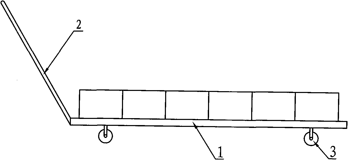
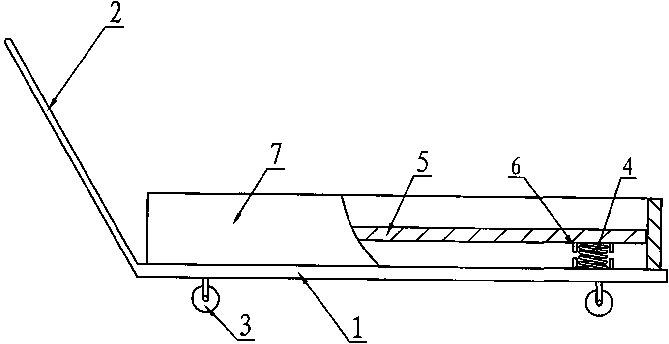
[0017] Embodiment 1: The shock-absorbing and anti-slip type silicon wafer process turnover trolley described in the present invention, as shown in Figure 2, it consists of a load-bearing base plate 1, a handle 2, swivel casters 3, a shock-absorbing elastic body 4, a loading plate 5, The limit seat cover 6 and the limit frame 7 are composed, the load-bearing base plate 1 is a rectangular plate, the handle 2 is fixedly connected with one side of the load-bearing base plate 1, and the connection angle between the handle 2 and the load-bearing base plate 1 is 110°~135°, and the handle 2 The height after installation is about 85cm. Four universal casters 3 are installed on the bottom surface of the load-bearing base 1 . The loading plate 5 is located above the load-bearing base 1 . , the shock-absorbing elastic body 4 is a shock-absorbing spring or an elastic rubber column, which is a shock-absorbing spring in this example, and a limit seat cover 6 is correspondingly provided on the...
Embodiment 2
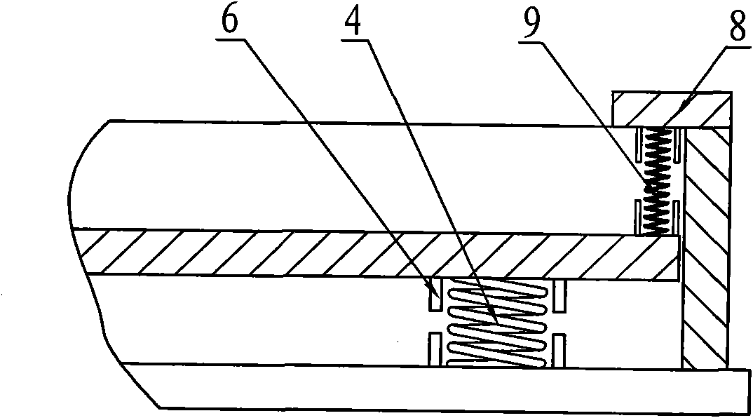
[0018] Embodiment 2: On the basis of Embodiment 1, two notch plates 8 are symmetrically installed on the upper opening of the limit frame 7, and a buffer spring 9 is set between the notch plate 8 and the loading plate 5, as Figure 3 shows.
PUM
 Abstract
Description
Claims
Application Information