
Three- impeller axial flow fan of subway traction motor brake cooling system

A traction motor and cooling system technology, applied in machines/engines, axial flow pumps, mechanical equipment, etc., can solve the problems of dynamic coordination, affecting fan efficiency, and high noise, reducing wind resistance coefficient, improving efficiency, and saving energy. Effect

Inactive Publication Date: 2010-09-15
HANGZHOU XIAOER SCI & TECH
View PDF4 Cites 3 Cited by
  • Summary
  • Abstract
  • Description
  • Claims
  • Application Information

AI Technical Summary

Problems solved by technology

However, although the axial support plate of the motor in the background technology is designed as a streamlined guide plate according to the airflow direction, because the streamlined guide plate is a fixed guide plate, the angle of its guide is a fixed angle, and it cannot form a dynamic fit with the front and rear impellers. , so it is inevitable to generate wind resistance, which not only directly affects the efficiency of the fan, but also has a large noise

Method used


Image

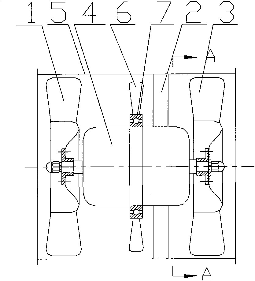
  • Three- impeller axial flow fan of subway traction motor brake cooling system
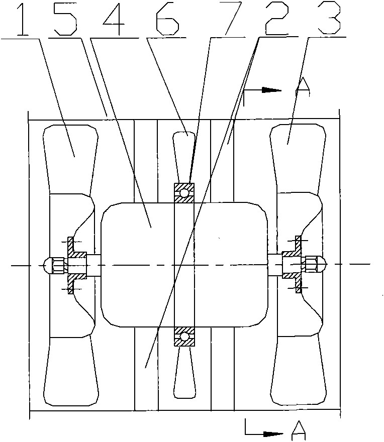
  • Three- impeller axial flow fan of subway traction motor brake cooling system
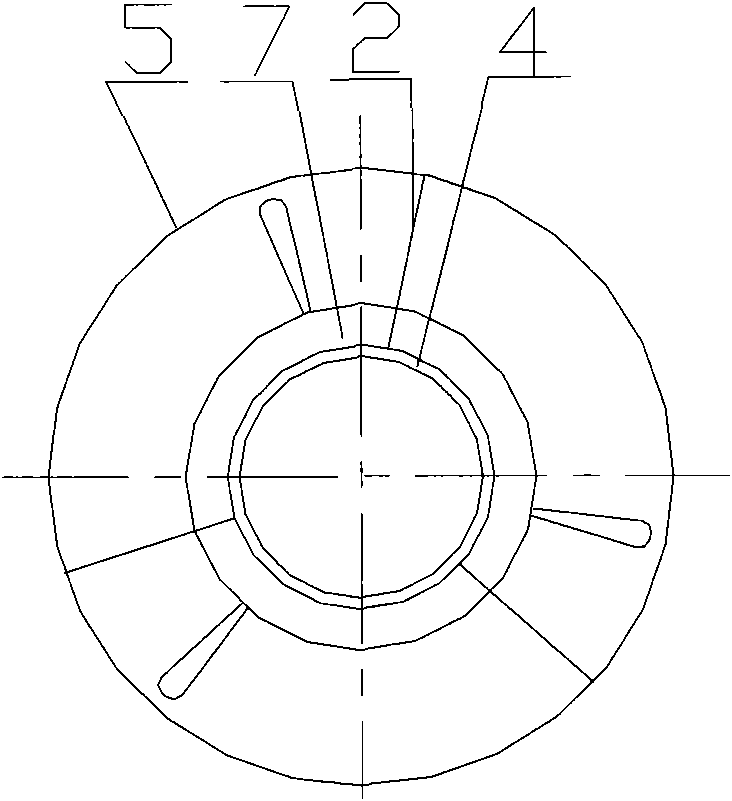
  • Three- impeller axial flow fan of subway traction motor brake cooling system

Examples


Embodiment 2

[0012] Embodiment 2: with reference to attached figure 2 . On the basis of Example 1, three streamlined deflectors 2 are used on both sides of the impeller 6 to fix the motor 4 in the axial flow fan casing 5, that is, the six streamlined deflectors 2 are divided into two groups, respectively located at The two sides of the impeller 6 and the motor 4 are fixed in the axial flow fan housing 5 .

Embodiment 3

[0013] Embodiment 3: On the basis of Embodiment 1, the air-cooling method of the three-blade axial flow fan in the brake cooling system of the subway traction motor, the air volume generated by the rotation of the front impeller 1 on the coaxial motor 4 in the three-blade axial flow fan passes through The impeller 6 leads to the rear impeller 3 and is led out by the rear impeller 3 .

Embodiment 4

[0014] Embodiment 4: On the basis of Embodiment 3, the air volume generated by the rotation of the front impeller 1 on the coaxial motor 4 in the three-blade axial flow fan is rectified and guided to the impeller 6 through the streamlined deflector 2 and guided through the impeller 6 To the rear impeller 3, and derived from the rear impeller 3.

[0015] Embodiment 4: On the basis of Embodiments 2 and 3, the air volume generated by the rotation of the front impeller 1 on the coaxial motor 4 in the three-blade axial flow fan is rectified and guided to the impeller 6 through the streamlined deflector 2, and then passed through After the secondary rectification of the streamlined deflector 2 , the flow is guided to the rear impeller 3 and is led out by the rear impeller 3 .


PUM


Abstract

The invention relates to a three-impeller axial flow fan of a subway traction motor brake cooling system, which can efficiently reduce the wind resistance and the fan noise and improve the fan efficiency, and comprises a double-impeller axial flow fan of the traction motor brake cooling system, wherein an impeller is installed on the machine body of a motor in the double-impeller axial flow fan. The invention has the advantages that: firstly, because the impeller located between a front impeller and a back impeller can form great dynamic match with the front impeller and the back impeller, and can avoid the disadvantages of the background technology basically so as to efficiently improve the efficiency of the fan, reduce the noise and the wind resistance of the fan and meet the requirements of the subway traction motor on brake and cooling; secondly, because the fan has lower wind resistance coefficient and higher efficiency, the purpose of saving energy is achieved; thirdly, due to the arrangement of a streamline-shaped guide plate, the purpose of fixing the three-impeller axial flow fan is realized, and the function of rectification is also realized, such that the three-impeller axial flow fan realizes the purpose of flow stabilization, high speed and powerfulness.

Description

technical field [0001] The invention relates to a three-blade axial flow fan for a subway traction motor brake cooling system that can not only form dynamic matching with the front and rear impellers in the double-blade axial flow impeller, but also can effectively reduce wind resistance, reduce fan noise, and improve fan efficiency. It is mainly used in the brake cooling system of subway traction motors and belongs to the field of axial flow fan manufacturing. Background technique [0002] Authorized announcement number CN100445569C, name "Traction motor brake cooling system double impeller axial flow fan", based on the existing axial flow fan including the casing, front and rear impellers and motor, the axial support plate of the motor is changed according to the direction of airflow The designed streamlined guide plate, the motor support plate and the streamlined guide vanes distributed on the outer periphery of the motor and fixed on the casing together form the middle g...

Claims


Application Information

Patent Timeline
Patent Type & Authority Applications(China)
IPC IPC(8): F04D25/08F04D19/00F04D29/34F04D29/38F04D29/54
Inventor 翟俊琳
Owner HANGZHOU XIAOER SCI & TECH
Learn More