Fiber Bragg grating strain sensor

A technology of strain sensor and fiber grating, applied in the direction of instruments, optical devices, measuring devices, etc., can solve the problems of large-scale structural network monitoring that cannot be long-distance, complex structure, complex shielding packaging, etc., to improve strain monitoring performance , Eliminate electromagnetic interference and ensure the effect of monitoring data

Inactive Publication Date: 2010-09-15
BEIJING PI OPTICS
View PDF0 Cites 23 Cited by
  • Summary
  • Abstract
  • Description
  • Claims
  • Application Information

AI Technical Summary

Problems solved by technology

It can be seen that in large-scale low-temperature projects, many materials and components are in various extreme environments such as ultra-low temperature, strong magnetic field, neutron irradiation, high pressure, vacuum, etc. It is difficult to achieve convenient and reliable prediction of their stress and strain distribution

Method used


Image

  • Fiber Bragg grating strain sensor
  • Fiber Bragg grating strain sensor
  • Fiber Bragg grating strain sensor

Examples


Embodiment Construction

[0020] An embodiment of the present invention provides a fiber grating strain sensor, which can realize online strain monitoring in large-scale low-temperature projects, effectively eliminate the influence of electromagnetic interference in complex and harsh environments, ensure reliable monitoring data, and improve strain monitoring performance.

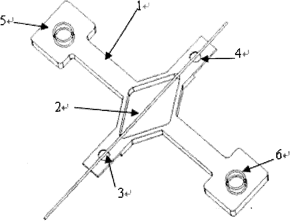
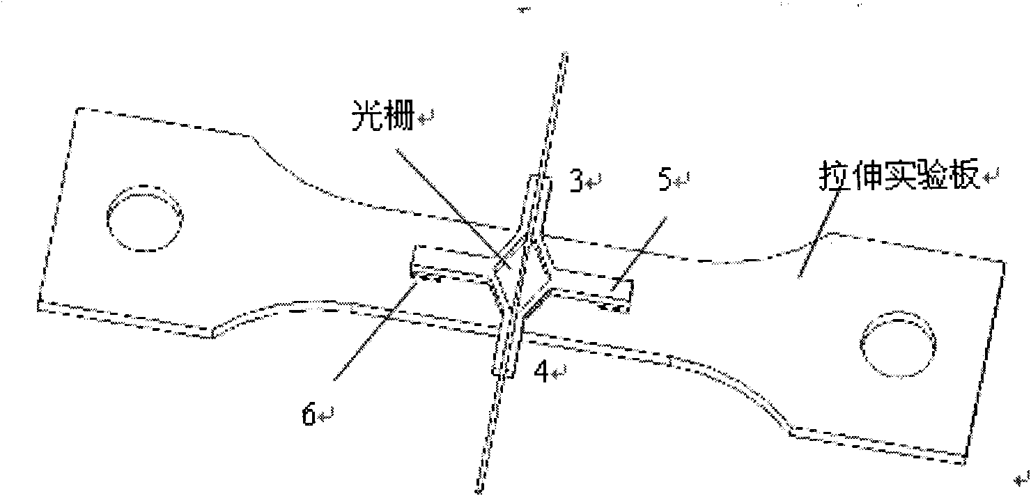
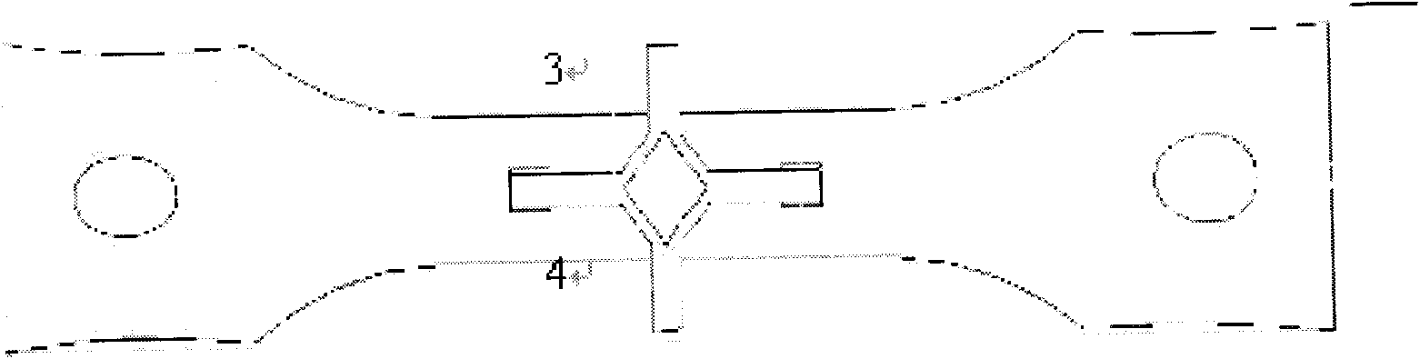
[0021] In order to better describe the embodiment of the present invention, the specific implementation manner of the present invention will be described in conjunction with the accompanying drawings, as follows figure 1 Shown is a schematic structural view of the fiber grating strain sensor provided by the embodiment of the present invention, figure 1 Including: rhombic strain base 1 and fiber Bragg grating 2, wherein:

[0022] The two ends of the grid area of ​​the fiber grating 2 are respectively fixed on one axis of the rhombic strained base 1. figure 1 The two ends of the gate region of the fiber grating 2 are fixed on 3 and 4...


PUM


Abstract

The embodiment of the invention provides a fiber Bragg grating strain sensor, the sensor comprises a diamond-shaped strain base and a fiber Bragg grating, wherein two ends of a grating region of the fiber Bragg grating are respectively fixed on one shaft of the diamond-shaped strain base; and the other shaft of the diamond-shaped strain base is respectively fixed on a measured basal body, and the diamond-shaped strain base can convert the deformation of the diamond-shaped strain base to the wave length change of the fiber Bragg grating. The fiber Bragg grating strain sensor can provide the fiber Bragg grating sensor which can carry out strain on-line monitoring under a large cryogenic project through the structure of the sensor, thereby effectively eliminating the impacts of electromagnetic interference under the complicated harsh environment, ensuring the reliability of monitoring data and improving the strain monitoring performance.

Description

technical field [0001] The invention relates to the field of optical fiber sensors, in particular to an optical fiber grating strain sensor. Background technique [0002] At present, complex operating environments are involved in large-scale cryogenic projects such as aerospace technology, accelerators, fusion reactors, spallation neutron sources, and large superconducting magnets. Among them, the most important thing is the mechanical properties of the components, because in the environment of low temperature, irradiation, magnetic field, high current, etc., the failure behaviors of components such as stress, strain corrosion, quench, creep, and fatigue fracture are the main causes of system damage. reason. [0003] For the liquid hydrogen and liquid oxygen engines of launch vehicles in aerospace technology, space shuttle fuel tanks, wing insulation panels, etc., it is not only necessary to monitor the temperature, but more importantly, to monitor the parameters of stress ...

Claims


Application Information

Patent Timeline
IPC IPC(8): G01B11/16
Inventor 倪正华叶晓平
Owner BEIJING PI OPTICS
Why Eureka
Try Eureka