Regulatable Hall effect sensor

A Hall-effect sensor technology, applied in adjustable Hall-effect sensor, automotive cam and crankshaft speed/position detection field, can solve the problems of unadjustable switch point, narrow range of use, prone to malfunction, etc. Vibration performance, a wide range of applications, the effect of ensuring stability

Inactive Publication Date: 2010-09-15
杭州鑫芯电子有限公司
View PDF8 Cites 10 Cited by
  • Summary
  • Abstract
  • Description
  • Claims
  • Application Information

AI Technical Summary

Problems solved by technology

The existing Hall effect sensor is generally of the external magnetic type. There is no magnetic block installed at the position of the Hall effect sensor, but a magnetic block is provided corresponding to the mechanical device that moves relative to it. Therefore, the current Hall effect sensor The sensor is usually sold with a magnetic strip made of powder metallurgy material. The installation is subject to certain restrictions, the anti-interference ability is poor, and the interference of dust and oil will lead to inaccurate detection signals, prone to misoperation, and poor anti-vibration effect.
And the current hall effect sensor with built-in magnetic steel also has its obvious deficiencies, such as the patent ZL02112326. A Hall element, the magnetic block is arranged on both sides of the Hall element according to the magnetic opposite, the Hall element and the magnetic block are packaged in the front end of the same housing, and the front wall of the housing is a non-magnetic material, another type of the patent The way to realize it is to use two Hall elements, set the sensing surface back to back, and face the two Hall elements facing forward and backward respectively. When the magnetizer approaches or leaves from the front of the housing, the two Hall elements will The increase or decrease of the magnetic field is sensed separately, thus forming a differential output mode
However, this design requires two magnets plus one or two Hall elements, which are packaged in the shell. The magnet and Hall element must be in a fixed position, the switch point cannot be adjusted, and the scope of use is relatively narrow. Production and installation Slightly complicated, large in size and high in cost

Method used


Image

  • Regulatable Hall effect sensor
  • Regulatable Hall effect sensor
  • Regulatable Hall effect sensor

Examples


Embodiment

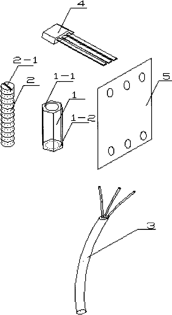
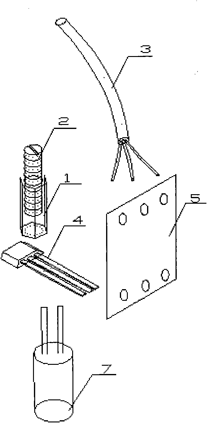
[0021] Such as figure 1 As shown, this embodiment is composed of lead wire group 3, printed circuit board 5, Hall element 4, magnetic steel sleeve 1, and magnetic steel 2. The magnetic steel 2 is a cylindrical permanent magnet, which is arranged on the outer surface of the magnetic steel 2. There are external threads, and a groove 2-1 is provided on the upper surface of the magnetic steel 2. The magnetic steel sleeve 1 is made of copper without magnetism. The magnetic steel sleeve 1 is hollow, and the hollow part is provided with internal threads. The internal thread and the magnetic steel 2 external threads cooperate with each other. The magnetic steel 2 is installed in the magnetic steel cover 1, and the groove 2-1 faces upward. The magnetic steel cover 1, the lead wire group 3 and the Hall element 4 are all welded on the printed circuit board 5, and the lower bottom surface 1-2 of the magnetic steel cover 1 and the Hall element 4 are close to each other.

[0022] As a spe...


PUM


Abstract

The invention relates to a regulatable Hall effect sensor which is used for distance detection, speed detection, angle detection and rotating speed detection, and is particularly applied to the fields of automotive cam and crankshaft speed/position detection, speedometers used in automobiles and industries, and the like. The regulatable Hall effect sensor comprises a lead wire set, a printed-circuit board and a Hall element, wherein, the lead wire set and the Hall element are respectively fixed on the printed-circuit board, and also are provided with magnetic steel sleeves and magnetic steel; the magnetic steel is arranged in the magnetic steel sleeve, is made of permanent magnet materials, and is provided with external screw threads; the magnetic steel sleeve is made of nonmagnetic materials, and is provided with internal screw threads; the external screw threads are matched with the internal screw threads; the magnetic steel sleeve is fixedly connected on the printed-circuit board; and the lower bottom surface of the magnetic steel sleeve is connected with the Hall element.

Description

technical field [0001] The invention relates to an adjustable Hall effect sensor, which is an adjustable Hall effect sensor used for distance detection, speed detection, angle detection and rotational speed detection. It is specifically used in automotive cam and crankshaft speed / position detection, automotive and industrial speedometers and other fields. Background technique [0002] A Hall Effect sensor uses a Hall element to generate a signal from a change in the magnetic field at its location. The existing Hall effect sensor is generally of the external magnetic type. There is no magnetic block installed at the position of the Hall effect sensor, but a magnetic block is provided corresponding to the mechanical device that moves relative to it. Therefore, the current Hall effect sensor When the sensor is sold, it usually comes with a magnetic strip made of powder metallurgy. The installation is limited, the anti-interference ability is poor, and the interference of dust ...

Claims


Application Information

Patent Timeline
Patent Type & Authority Applications(China)
IPC IPC(8): G01D5/12
Inventor 管慧李晓宏张琪
Owner 杭州鑫芯电子有限公司
Why Eureka
Try Eureka