Device for measuring effective value of alternating current for experimental teaching

A measuring device and alternating current technology, applied in the field of electrical teaching aids, can solve problems such as inability to use alternating current for experimental teaching, poor preparation of experimental equipment, troublesome experimental operation, etc., to improve demonstration efficiency and effect, simple and reasonable structure, and small experimental error. Effect

Inactive Publication Date: 2010-09-15
缪庚平
View PDF8 Cites 7 Cited by
  • Summary
  • Abstract
  • Description
  • Claims
  • Application Information

AI Technical Summary

Problems solved by technology

However, there are following disadvantages in adopting the above-mentioned method for experimentation: the first is that the experimental equipment is not easy to prepare, and the experimental operation is very troublesome, time-consuming, and the experimental efficiency is low; It is difficult to support the conclusion that "the effective value of alternating current is determined by the thermal effect of current"
[0003] In the prior

Method used


Image

  • Device for measuring effective value of alternating current for experimental teaching
  • Device for measuring effective value of alternating current for experimental teaching
  • Device for measuring effective value of alternating current for experimental teaching

Examples


Embodiment

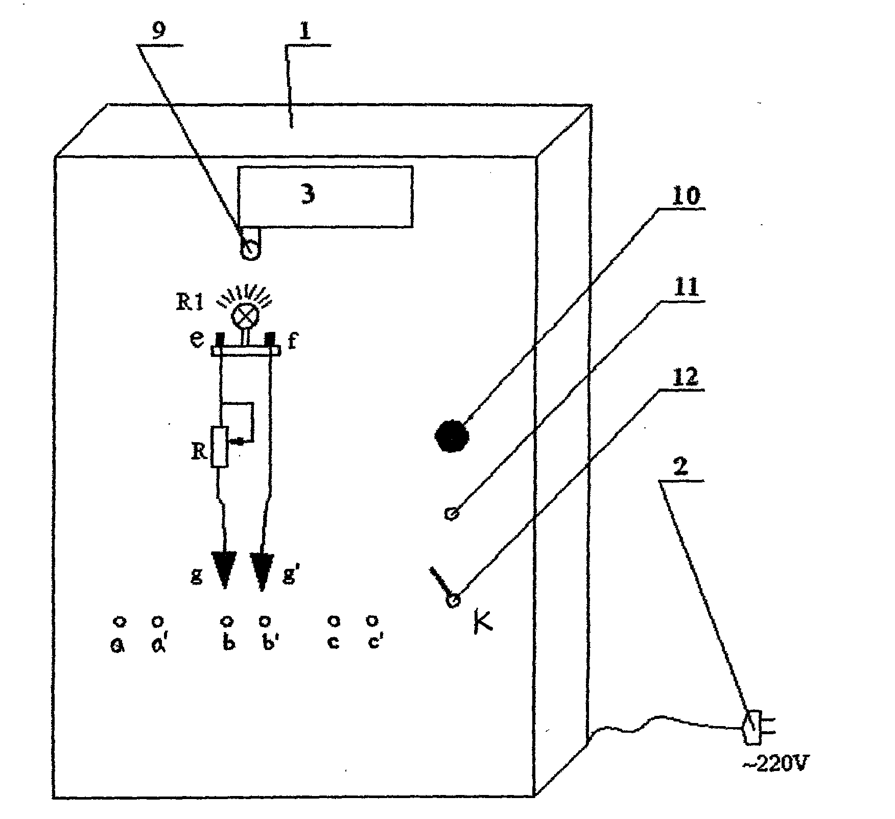
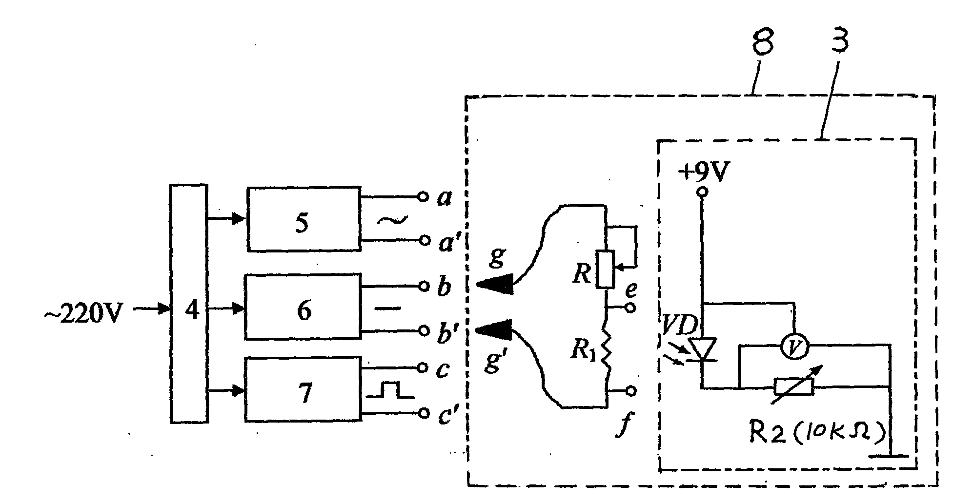
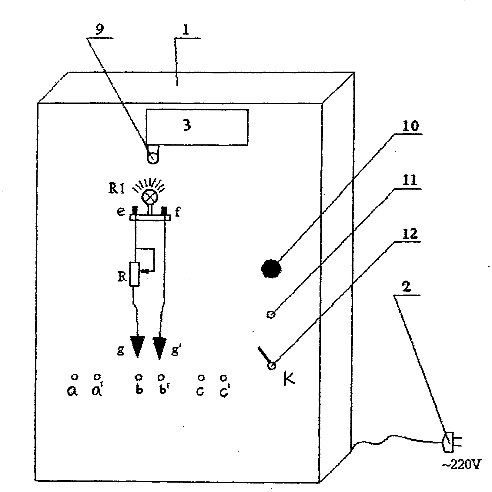
[0023] Referring to the accompanying drawings, when the resistive element R1 uses a 2.5V0.3A light bulb and the thermal effect measuring device 3 uses an infrared photodiode VD as a self-made measuring device for the experiment, first clip the alligator clips g and g' to the sinusoidal AC output wiring pile On aa', provide sinusoidal alternating current to the bulb R1, adjust the sliding rheostat R, and read the maximum voltage U of the sinusoidal alternating current at both ends of the bulb R1 from the oscilloscope used in conjunction with the thermal effect measuring device 3 mAt the same time, write down the reading N on the thermal effect measuring device 3 at this time; then clamp the alligator clips g and g' to the DC output terminal bb', supply DC power to the bulb R1, adjust the sliding rheostat R, and make the thermal effect measuring device 3 The reading is still N, and then read the DC voltage value U at this time from the oscilloscope. Since the readings on the two...


PUM


Abstract

The invention discloses a device for measuring effective value of alternating current for experimental teaching. The device is characterized in that the front of an outer shell is provided with a resistance component R1, a rheostat R and three pairs of output wiring piles aa', bb' and cc' of three types of power supplies of sine alternating current, direct current and rectangular alternating current, one end of the rheostat R is connected with a wiring pile e of the resistance component R1, the other end of the rheostat R is connected with a crocodile clip g which is used as a jointing clamp, a wiring pile f of the R1 is connected with another crocodile clip g', the resistance component R1 is right opposite to a probe of a thermal effect measuring device, the wiring piles e and f of the R1 are connected with an oscilloscope, the crocodile clips g and g' can be respectively clamped to the three pairs of the wiring piles of aa', bb' and cc' of the three types of the power supplies as required by an experiment, and the numerical reading on the thermal effect measuring device is in one-one correspondence relation with the effective value of the voltage on the resistance component R1. The technology can completely display the structuring process of the abstract conception of the effective value of the alternating current, truly realize the experimental teaching of the effective value of the alternating current, is beneficial to enhancing the perceptual knowledge of the students and has reasonable structure, convenient and quick operation and small experimental errors.

Description

(1) Technical field [0001] The invention relates to an electrical teaching aid, in particular to a device for measuring the effective value of alternating current (or called an alternating current effective value demonstrator) for experimental teaching, which is suitable for use as an experimental teaching demonstration instrument for the effective value of alternating current in high school physics. (2) Background technology [0002] The effective value of alternating current is a knowledge point that students must master in high school physics courses, but it is difficult for many students to understand the abstract concept of effective value of alternating current in high school physics teaching, and there is no corresponding teaching aid in the middle school physics teaching instrument catalog , which restricts the development of experimental teaching of this knowledge point, making it impossible for students to intuitively understand the concept of effective value of alt...

Claims


Application Information

Patent Timeline
IPC IPC(8): G01R19/02G09B23/18
Inventor 缪庚平
Owner 缪庚平
Why Eureka
Try Eureka