Acoustic wave transducer

An acoustic transducer and transducer technology, applied in seismology for well logging records, etc., can solve the problem of fragmentation of transmitting crystals, small elastic deformation of apron 8, unfavorable routing of receiving transducer 5 and Assembly and other issues, to achieve the effect of increasing the amount of elastic deformation, reducing the amount of overall deformation, and facilitating wiring and assembly

Inactive Publication Date: 2010-09-15
CHINA NAT OFFSHORE OIL CORP +1
View PDF2 Cites 7 Cited by
  • Summary
  • Abstract
  • Description
  • Claims
  • Application Information

AI Technical Summary

Problems solved by technology

When the slotted shell 1 of the acoustic wave transducer is deformed, it is easy to cause the receiving transducer 5 to deform, thereby affecting the performance of the receiving transducer 5
In addition, this structure is very unfavorable to the wiring and assembly of the receiving transducer 5, and it is very troublesome in the actual operation process.
[0004] The transmitting transducer 6 in the traditional acoustic wave transducer is as figure 1 , image 3 As shown, the two ends of the transmitting transducer 6 are fixed in the slotted shell 1 by threads, which are easily affected by the deformation of the slotted shell 1, thereby affecting the performance of the transmitting transducer 6
Especially when carrying the acoustic wave transducer, since the acoustic wave transducer is slender, it will be bent, and the transmission to the emitting transducer 6 will cause the emitting crystal 7 to break
In addition, the emitting crystal 7 of the emitting transducer 6 is elastically fixed only by the apron 8. Since the elastic deformation of the apron 8 is relatively small, when the emitting crystal 7 has a large deformation, the problem of fragmentation of the emitting crystal is very likely to occur. cause unnecessary loss

Method used


Image

  • Acoustic wave transducer
  • Acoustic wave transducer
  • Acoustic wave transducer

Examples


Embodiment Construction

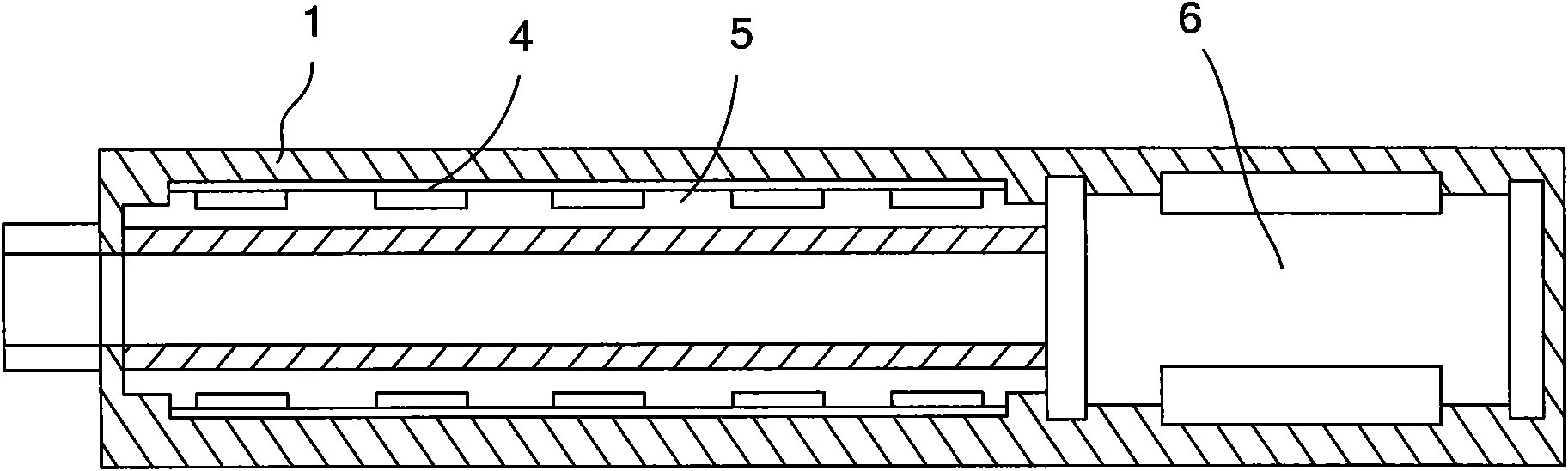
[0032] Such as Figure 4 As shown, the present invention includes a slotted housing 1, a receiving transducer module 2, a transmitting transducer 3, and a bladder 4. The slotted shell 1 is a shell of the present invention. In order to improve the sound insulation effect of the slotted shell 1, a plurality of slot holes 11 are provided on the slotted shell 1.

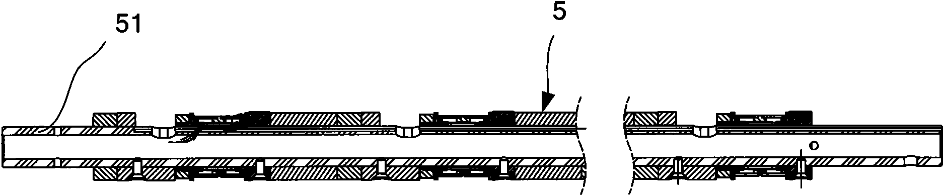
[0033] The receiving transducer module 2 is set in the slotted housing 1 for receiving signals. The receiving transducer module 2 includes two or more receiving transducers 21, which are connected in series by threads.

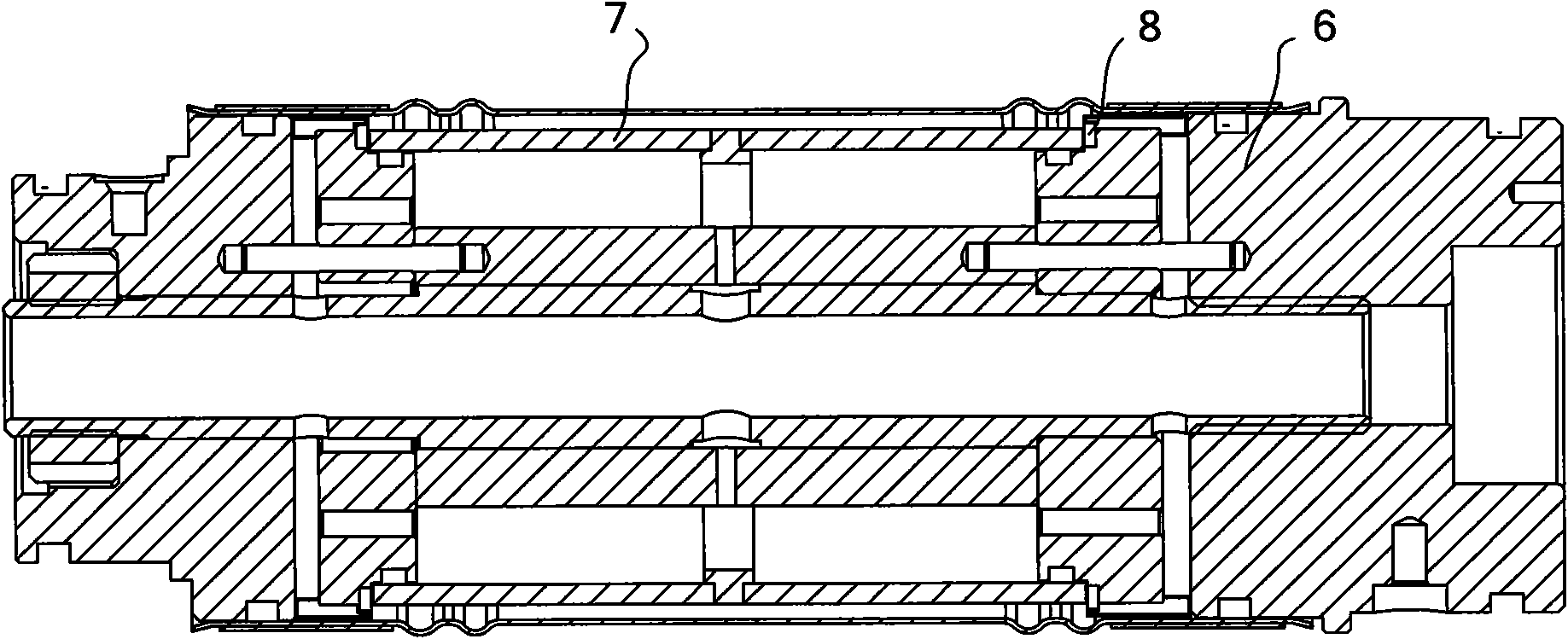
[0034] The transmitting transducer 3 is arranged on the side of the receiving transducer module 2 and is nested in the slotted housing 1 like the receiving transducer module 2. One end of the transmitting transducer 3 is fixedly connected with the slotted housing 1, and the other end is a free end.

[0035] The bladder 4 is a flexible piece, and is set in the slotted shell 1 to wrap and receive the transducer...


PUM


Abstract

The invention provides an acoustic wave transducer. The transducer comprises a notched shell, a receiving transducer module, a transmitting transducer and a bag, wherein the notched shell is provided with slotted holes for improving the acoustical insulation effect of the notched shell; the receiving transducer module is sleeved in the notched shell and comprises more than two receiving transducers sequentially connected together in series through screw threads; the transmitting transducer of which one end is fixedly connected to the interior of the notched shell is sleeved in the notched shell and arranged on one side of the receiving transducer module; the bag is a flexible part, and is sleeved in the notched shell and wrapped around the receiving transducer module; and oil is filled in the bag. In the transducer, as the receiving transducer module comprises more than two receiving transducers sequentially connected in series through the screw threads, each transducer can be assembled singly and conveniently; the deformation of each transducer is not accumulated during the deformation of the notched shell, so the overall deformation of the receiving transducer module is reduced; in addition, only one end of the transmitting transducer is fixedly connected with the notched shell, so the influence of the deformation of the notched shell on the transmitting transducer can be effectively avoided.

Description

Technical field [0001] The invention relates to an acoustic wave transducer. Background technique [0002] The structure of the traditional acoustic transducer is as figure 1 As shown, a slotted housing 1, a receiving transducer 5, a transmitting transducer 6 and a bladder 4 are included. The receiving transducer 5 and the transmitting transducer 6 are sleeved and fixed in the slotted housing 1 in parallel, and the bladder 4 is used to wrap the receiving transducer 5. [0003] The receiving transducer in the traditional acoustic wave transducer 5 such as figure 2 As shown, the receiving transducer 5 is formed integrally and rigidly connected by an internal mounting rod 51. When the grooved housing 1 of the acoustic wave transducer is deformed, the receiving transducer 5 is easily deformed, thereby affecting the performance of the receiving transducer 5. In addition, this structure is very unfavorable for the wiring and assembly of the receiving transducer 5, which is very troubl...

Claims


Application Information

Patent Timeline
Patent Type & Authority Applications(China)
IPC IPC(8): G01V1/52
Inventor 鲍忠利刘西恩于会媛陈洪海陶爱华罗瑜林
Owner CHINA NAT OFFSHORE OIL CORP
Why Eureka
Try Eureka