
Radio frequency indication test system and control method thereof

A test control and index test technology, applied in the field of communication, can solve the problems of complex overall system and high construction requirements, and achieve the effect of simplifying the structure and reducing construction requirements

Inactive Publication Date: 2010-09-15
HUAWEI TECH CO LTD
View PDF7 Cites 13 Cited by
  • Summary
  • Abstract
  • Description
  • Claims
  • Application Information

AI Technical Summary

Problems solved by technology

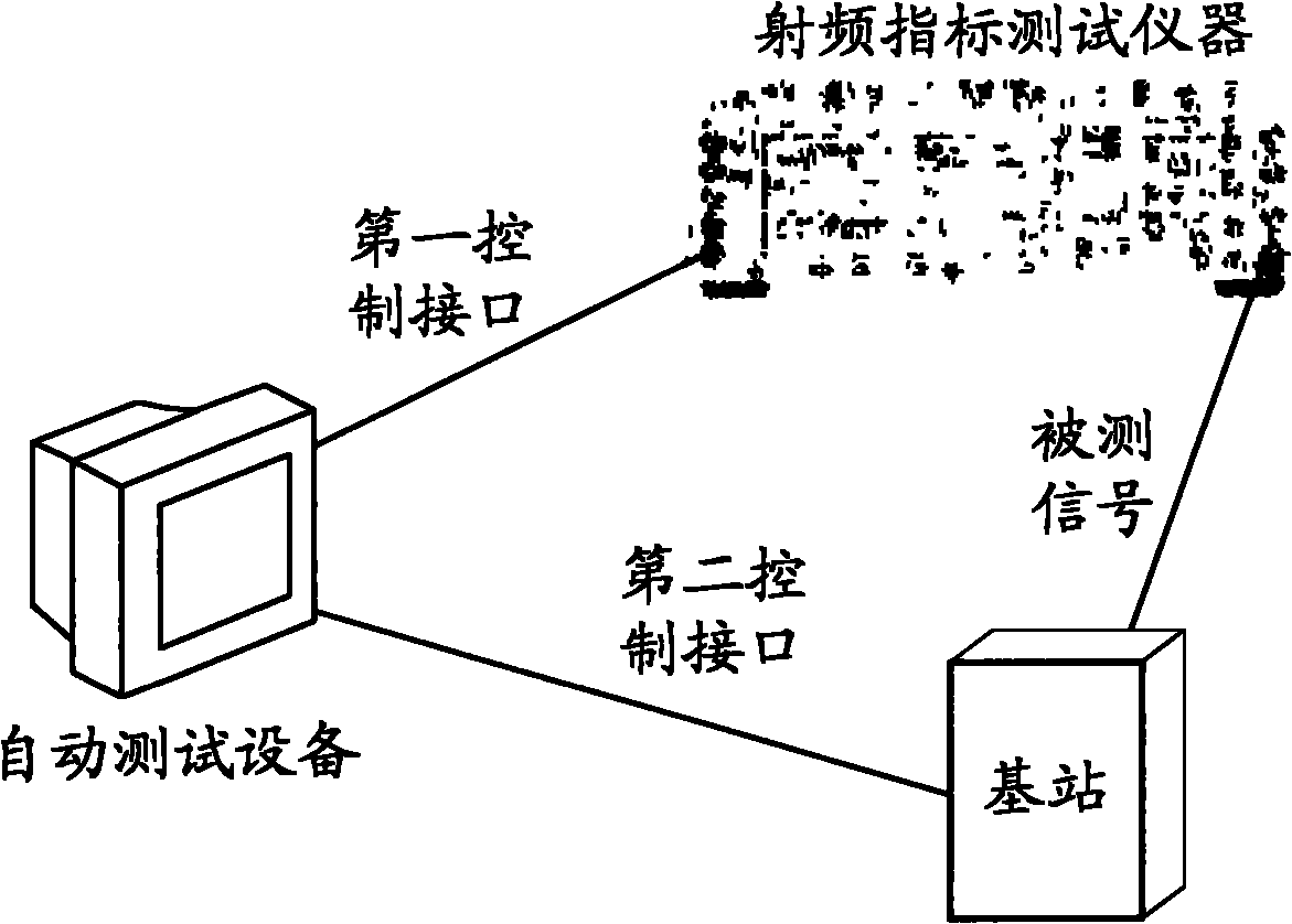
[0004] In this way, when performing radio frequency index testing through the ATE system, many interface configurations are required in both hardware configuration and software configuration. The overall system is complex, and the requirements for the production test environment and field test environment for radio frequency products such as base station deployment are relatively high.

Method used


Image

  • Radio frequency indication test system and control method thereof
  • Radio frequency indication test system and control method thereof
  • Radio frequency indication test system and control method thereof

Examples


Embodiment 1

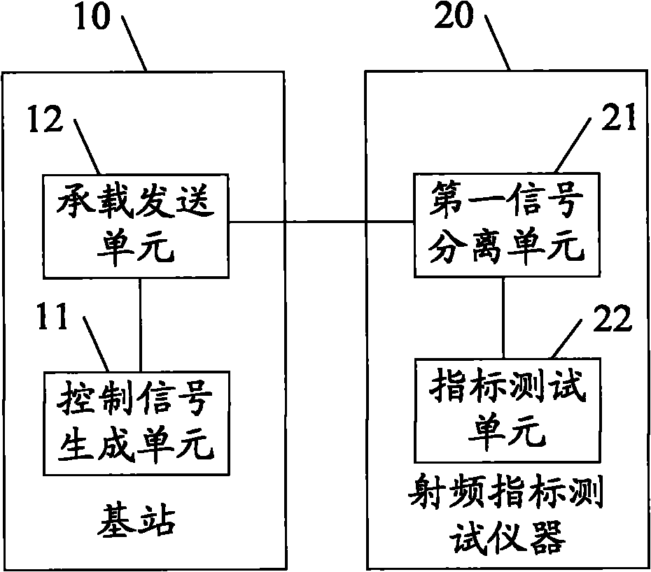
[0041] A radio frequency index test system, the structure diagram is as follows figure 2 As shown, including: base station 10, wherein:

[0042] The base station 10 is used to generate a test control signal, carry the measured signal and the test control signal to different frequency bands of the radio frequency signal, and send the carried radio frequency signal to the radio frequency index test instrument 20; so that the radio frequency index test instrument 20 according to the radio frequency signal The test control signal in controls the testing of the signal under test.

[0043] Here, the base station 10 and the radio frequency index tester 20 are directly connected through a radio frequency transmission line such as a radio frequency cable, and the test control signal is used to instruct the radio frequency index tester 20 to test the signal under test of the base station 10 .

[0044] It can be understood that the system also includes: a radio frequency indicator test...

Embodiment 2

[0113] A radio frequency index test system, the structure diagram is as follows Figure 5 As shown, it includes: a base station 10 and a radio frequency test conversion device 30; wherein: the radio frequency test conversion device 30 is connected to the radio frequency index test instrument 40 through a control transmission interface and a measured transmission interface, and is directly connected to the base station 10 through a radio frequency transmission line such as a radio frequency cable ;

[0114] The base station 10 is used to generate a test control signal, and the test control signal is used to instruct the radio frequency indicator testing instrument to test the signal under test of the base station; the test signal and the test control signal are carried to different frequency bands of the radio frequency signal, and the carried The radio frequency signal is sent to the radio frequency test conversion device 30;

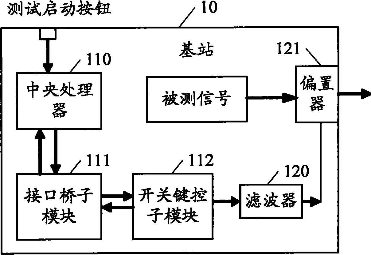
[0115] The specific structure of the base statio...


PUM


Abstract

The embodiment of the invention discloses a radio frequency indication test system and a control method thereof and belongs to the technical field of communication. The system of the embodiment of the invention comprises a base station, wherein the base station generates a test control signal; and the test control signal and a tested signal are loaded into different frequency ranges of a radio frequency signal, and the loaded radio frequency signal is sent to a radio frequency indication tester, so that the radio frequency indication tester controls the test for the tested signal according tothe test control signal. In the embodiment of the invention, the radio frequency product such as the base station can control the radio frequency indication tester to test the radio frequency productwithout extra control equipment, so that the structure for the radio frequency indication test is simplified, and construction requirements of a production test environment and a field test environment of the radio frequency product such as the base station opening are reduced.

Description

technical field [0001] The invention relates to the technical field of communication, in particular to a radio frequency index test system and a control method thereof. Background technique [0002] Such as figure 1 The shown automatic test equipment (Auto Test Equipment, ATE) system includes automatic test equipment, radio frequency index test equipment and radio frequency products such as base stations (Base Station, BS), wherein: the automatic test equipment controls the base station to the radio frequency index through the second control interface The test instrument provides test parameters; and controls the radio frequency index test instrument to test the radio frequency index of the base station through the first control interface; and the base station provides the tested signal to the radio frequency identification test instrument through a radio frequency signal (Radio Frequency, RF). [0003] The realization of above-mentioned test method needs to pass through th...

Claims


Application Information

Patent Timeline
Patent Type & Authority Applications(China)
IPC IPC(8): H04B17/00
Inventor 夏俊张勇
Owner HUAWEI TECH CO LTD
Learn More