Blast furnace bottom structure
A furnace bottom and blast furnace technology, applied in blast furnace, furnace bottom, blast furnace details, etc., can solve the problems of complex equipment cost and increase, and achieve the effect of reducing equipment cost and operating cost, easy manufacturing and improving operation efficiency.
- Summary
- Abstract
- Description
- Claims
- Application Information
AI Technical Summary
Benefits of technology
Problems solved by technology
Method used
Image

Examples
no. 1 approach
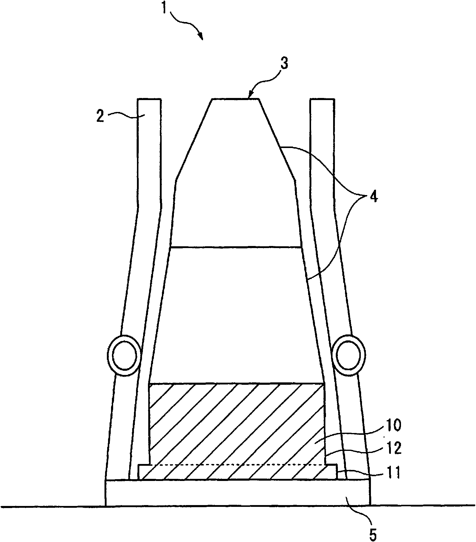
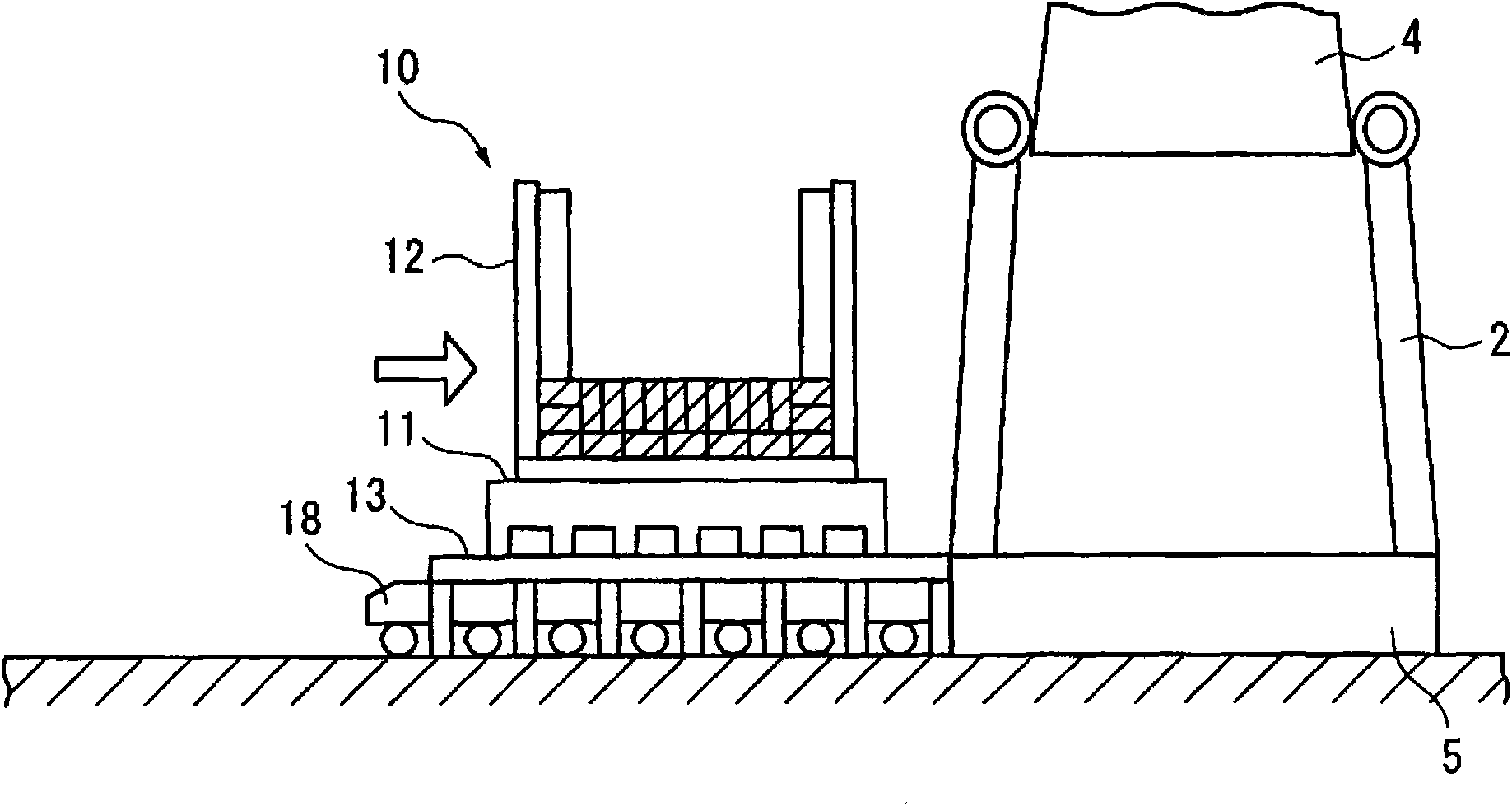
[0089] figure 1 Among them, the dismantling and maintenance of the blast furnace 1 is to cut the furnace body 3 built in the furnace body tower 2 in the horizontal direction, divide it into several ring-shaped components 4 in the vertical direction, and transport them to the blast furnace furnace in sequence. base 5 exterior. On the other hand, the ring members 4 are manufactured in advance at a plurality of production sites other than the construction site of the blast furnace, and they are built on the furnace foundation 5 to construct a new furnace body 3 .
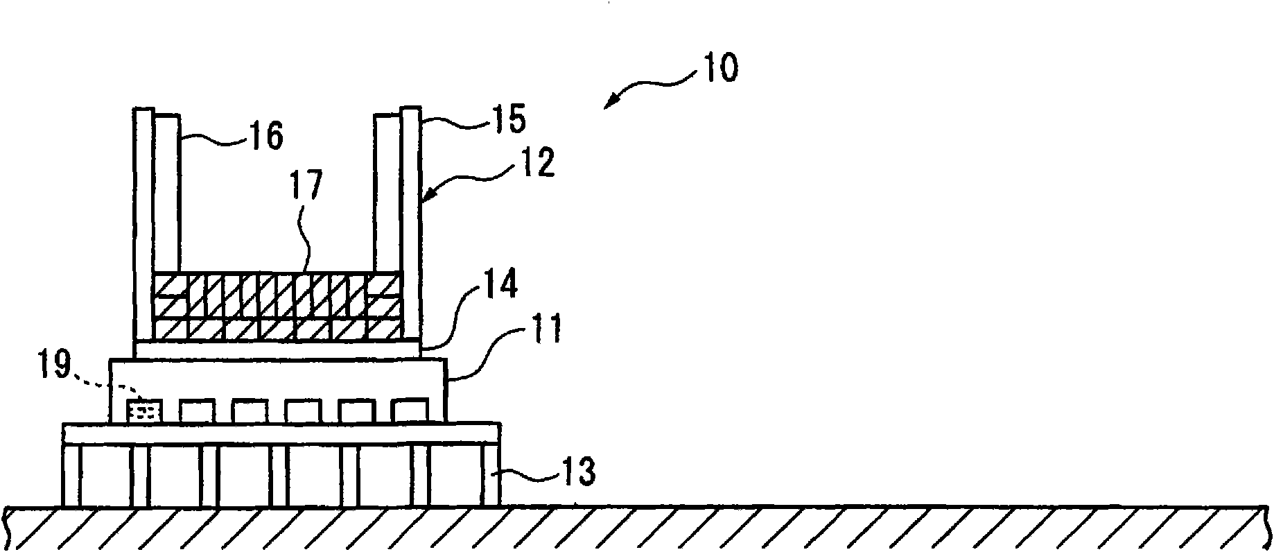
[0090] Among the annular components 4 , the furnace bottom ring beam 10 forms a furnace bottom structure 12 on the bottom beam 11 which belongs to the furnace bottom part of the furnace body 3 .
[0091] like figure 2 As shown, when the furnace bottom ring beam 10 is manufactured, the balance beam 13 is vertically set on the ground surface of the production site, and the bottom beam 11 is placed on the upper surfac...
no. 2 Embodiment approach
[0127] Figure 7 Among them, this embodiment has basically the same structure as the above-mentioned first embodiment. However, in the present embodiment, the cooling pipe 118 is not provided on the bottom girder 11 , and instead, a cooling pipe 53 as a heat transfer prevention mechanism is embedded along the supporting member 51 of the furnace foundation 5 .
[0128] In this embodiment, the support member 51 is cooled by the cooling pipe 53 , and the leg member 113 is also cooled via the support member 51 . Therefore, heat transfer from the leg member 113 is prevented by the cooling pipe 53 as a heat transfer prevention mechanism.
[0129] As the heat transfer preventing means, both the cooling pipe 53 on the furnace base 5 side and the cooling pipe 118 on the bottom beam 11 side may be used at the same time.
no. 3 Embodiment approach
[0131] Alternatively, a cooling pipe may be directly embedded in the leg member 113 to cool the leg member 113 itself.
[0132] Figure 8 Among them, this embodiment has basically the same structure as the above-mentioned first embodiment. However, in the present embodiment, the cooling pipe 118 is not provided on the bottom beam 11 , and instead, the cooling pipe 119 as a heat transfer prevention mechanism is directly embedded in the leg member 113 .
[0133] In this embodiment, the leg member 113 is cooled from the inside by the cooling pipe 119 . Therefore, the heat transfer from the leg member 113 can be prevented by the cooling pipe 119 as the heat transfer prevention mechanism.
[0134] As the heat transfer prevention means, either or both of the cooling pipe 119 in the leg member 113, the cooling pipe 53 on the side of the furnace base 5, and the cooling pipe 118 on the side of the bottom beam 11 may be used at the same time.
[0135] The leg member 113 incorporating...
PUM
 Abstract
Description
Claims
Application Information
 - R&D
- Intellectual Property
- Life Sciences
- Materials
- Tech Scout
- Unparalleled Data Quality
- Higher Quality Content
- 60% Fewer Hallucinations
Browse by: Latest US Patents, China's latest patents, Technical Efficacy Thesaurus, Application Domain, Technology Topic, Popular Technical Reports.
© 2025 PatSnap. All rights reserved.Legal|Privacy policy|Modern Slavery Act Transparency Statement|Sitemap|About US| Contact US: help@patsnap.com