Internal combustion engine

A technology for an internal combustion engine and an exhaust port, applied in the field of internal combustion engines, can solve problems such as unsatisfactory heat transmission, and achieve the effect of a simple structure condition

Inactive Publication Date: 2010-09-15
罗兰・柯克伯格
View PDF3 Cites 2 Cited by
  • Summary
  • Abstract
  • Description
  • Claims
  • Application Information

AI Technical Summary

Problems solved by technology

Pumping fresh air is clearly a disadvantage
Also, heat transmission

Method used


Image

  • Internal combustion engine
  • Internal combustion engine
  • Internal combustion engine

Examples


Embodiment Construction

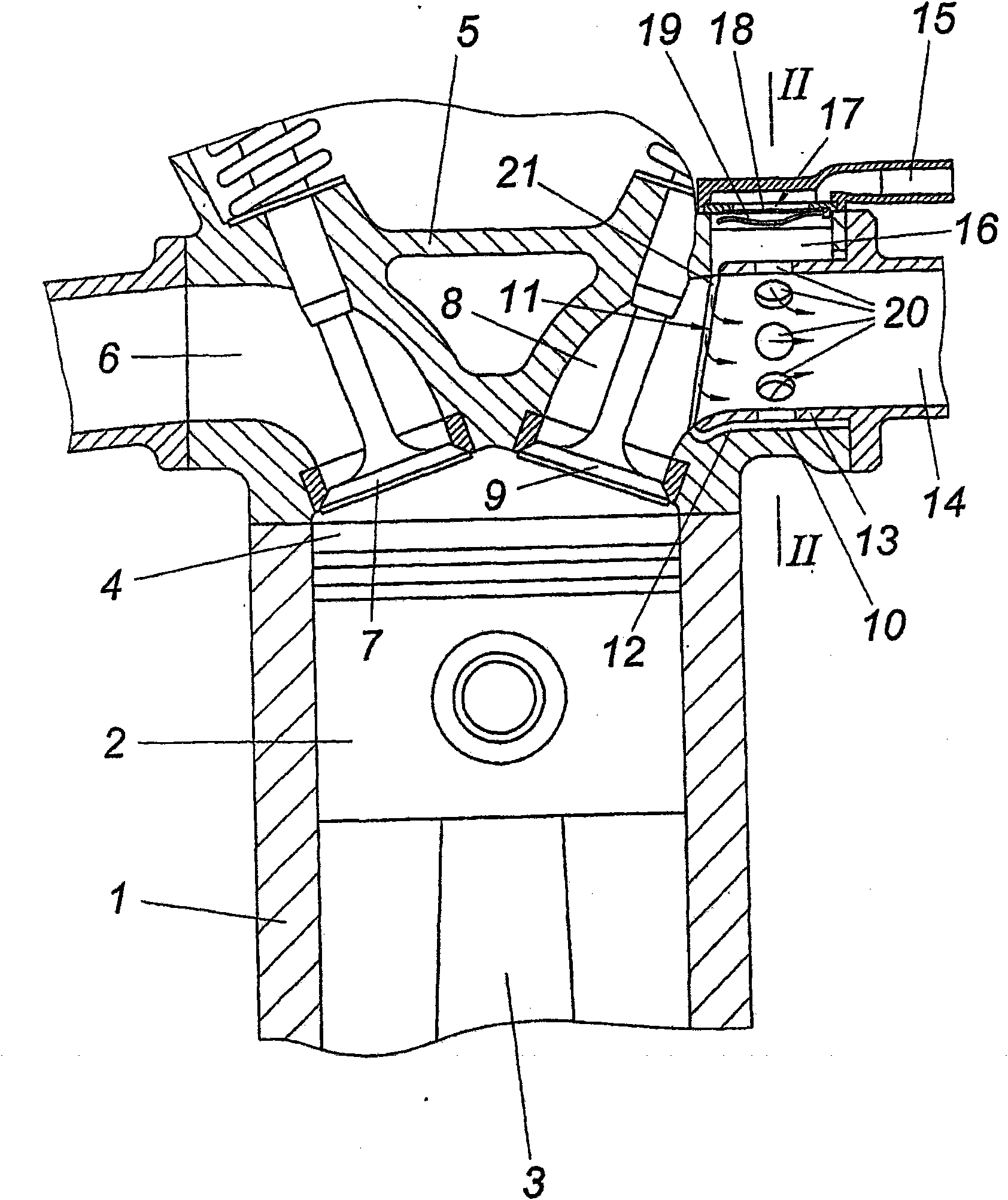
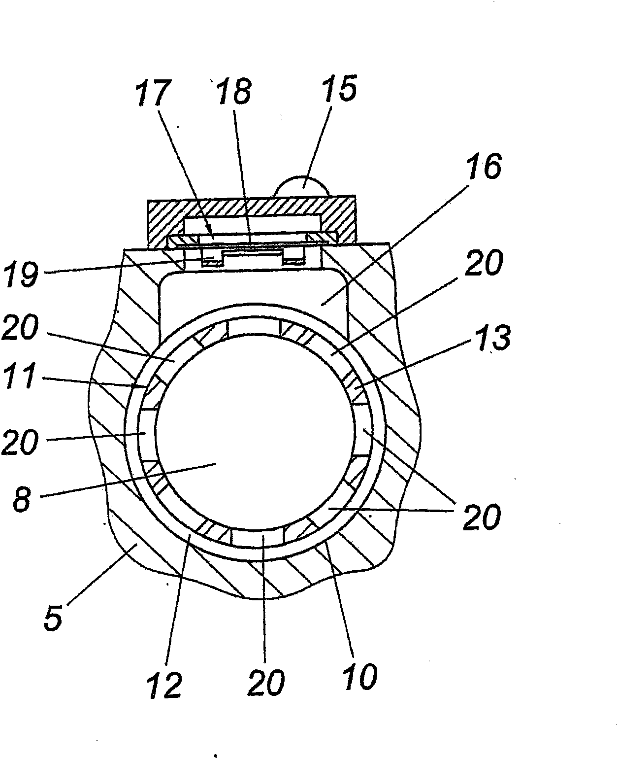
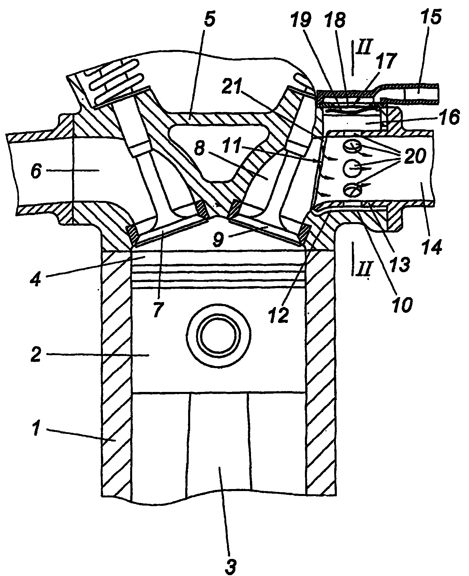
[0012] figure 1 The internal combustion engine shown has at least one cylinder 1 with a piston 2 which is connected via a connecting rod 3 to a crankshaft in a conventional manner. The combustion chamber of the cylinder 1 is closed upwards by a cylinder head 5 which is designed with at least one intake port 6 with intake valves 7 and at least one exhaust port 8 with exhaust valves 9 . The exhaust duct 8 comprises a tubular insert 11 which is accommodated in the cylinder head bore 10 , leaving an annular gap 12 between it and the cylinder head bore 10 . The insert 11 in the form of a connecting piece 13 is designed as a component of an exhaust manifold 14 which is connected to the exhaust duct 8 in a conventional manner via an exhaust elbow.

[0013] The annular gap 12 is connected with an air pipe 15 through which fresh air is fed into the exhaust branch pipe 14 for supplementary combustion of combustible residual substances. Here, the arrangement is such that the annular ga...


PUM


Abstract

An internal combustion engine is described having at least one cylinder (1), the cylinder head (5) of which forms at least one outlet channel (8) which merges into an exhaust-gas section (14) and comprises a tubular insert (11) which is arranged within a cylinder-head opening (10) with the formation of an annular gap (12), wherein the annular gap (12) which is fluid-connected to the outlet channel (8) is attached to an air line (15). In order to provide advantageous air feed conditions, it is proposed that the tubular insert (11) is part of the exhaust-gas section (14), and that the annular gap (12) is widened in the opening region of the air line (15) to form a chamber (16) which is delimited by a diaphragm valve (17) with respect to the air line (15).

Description

technical field [0001] The invention relates to an internal combustion engine having at least one cylinder, the cylinder head of which constitutes at least one exhaust duct leading into an exhaust manifold, the exhaust duct comprising a tubular tube which is arranged in the bore of the cylinder head to form an annular gap An insert, wherein the annular gap, which is in flow connection with the exhaust duct, is connected to the air line. Background technique [0002] In order to reduce the emission of environmentally polluting substances of internal combustion engines, it is known (US4437305A, US4727717A) that fresh air is supplied to the exhaust gas through an air pipe controlled by a diaphragm valve in the suction area according to the pressure conditions in the exhaust gas passage, for use when necessary Afterburning, for example, hydrocarbons or carbon monoxide in the exhaust manifold with the support of a catalyst. Because the desired oxidation is related to temperature...

Claims


Application Information

Patent Timeline
IPC IPC(8): F01N3/34F02F1/42F01N7/10F01N13/10
CPCF01N13/10F01N3/34Y02T10/20Y02T10/12
Inventor 罗兰·柯克伯格
Owner 罗兰・柯克伯格
Why Eureka
Try Eureka