Acetabulum reconstruction bracket for revision of total hip arthroplasty

A hip joint and acetabular technology, applied in the field of acetabular reconstruction bracket, can solve the problems of narrow range of flexion and movement of saddle-shaped prosthesis, poor supporting effect of double-layer metal mesh, and unguaranteed initial stability, etc. Difficult, firm support, easy placement

Inactive Publication Date: 2010-09-22
THYTEC SHANGHAI
View PDF4 Cites 2 Cited by
  • Summary
  • Abstract
  • Description
  • Claims
  • Application Information

AI Technical Summary

Problems solved by technology

The supporting effect of the double-layer metal mesh cover is poor, and the initial stability cannot be guaranteed; the disadvantage of the acetabular reinforcing ring cover is that it is difficult to place, which not only needs to meet the needs of the support f

Method used


Image

  • Acetabulum reconstruction bracket for revision of total hip arthroplasty
  • Acetabulum reconstruction bracket for revision of total hip arthroplasty
  • Acetabulum reconstruction bracket for revision of total hip arthroplasty

Examples


Embodiment 1

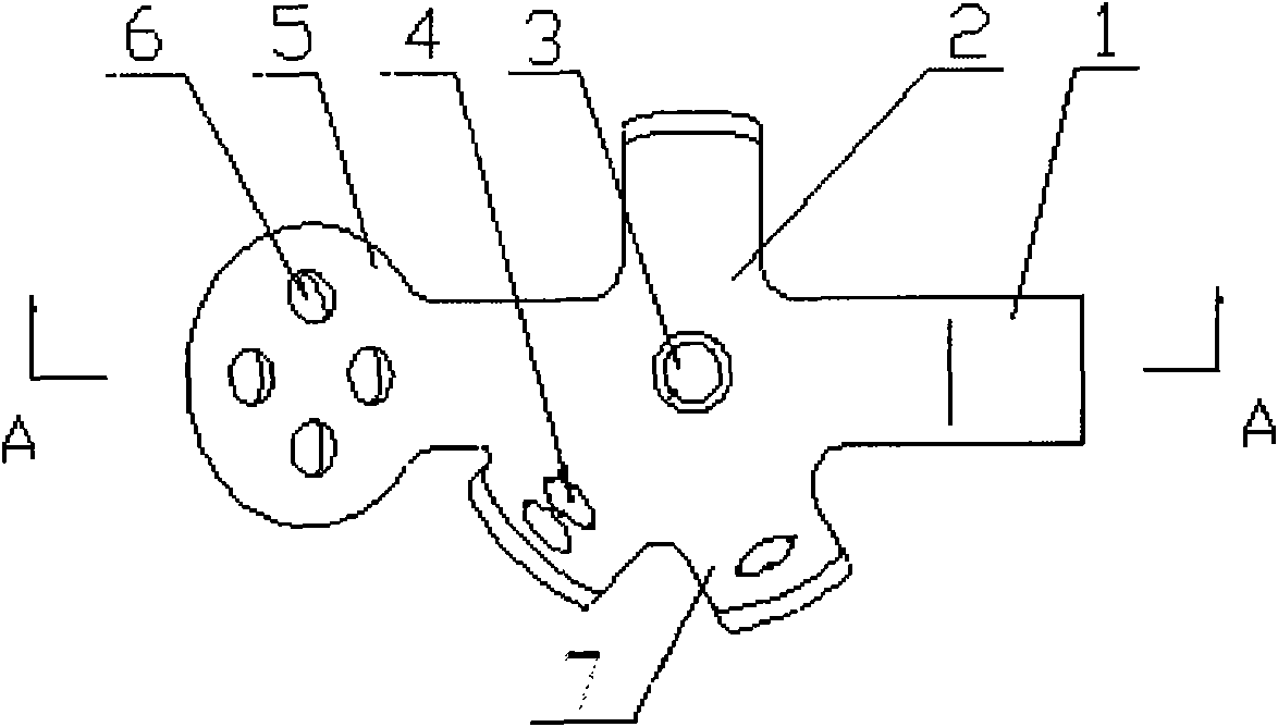
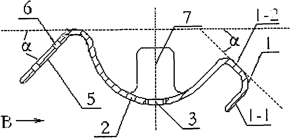
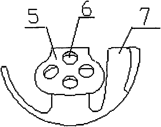
[0020] Figure 1 to Figure 3 It is a schematic diagram of the first embodiment of the present invention. It can be seen from the figure: an acetabular reconstruction stent for total hip arthroplasty, which is characterized in that the upper wing 5, the stent body 2, and the lower wing hook 1 are connected in sequence, so The upper side wing 5, the leaf-shaped side wing 7 provided around the bracket body 2, and the lower wing hook 1 are bent to the same side and are cup-shaped; the other end of the lower wing hook 1 faces the rear side of the bracket body 2 The curve is in a ∏ shape, and the round end of the upper wing 5 is bent toward the bottom of the cup-shaped bracket body 2; the surface of the round end of the upper wing 5 is provided with an oblique hole 6.

[0021] Such as figure 2 As shown, in the first embodiment, when the cup opening of the cup-shaped bracket body 2 is upward and perpendicular to the ground, the angle α between the center line of the upper side wing 5 a...

Embodiment 2

[0027] Figure 4 It is a schematic diagram of another structural form of the present invention. The second embodiment is basically the same as the first embodiment. Figure 4 versus figure 1 The structural difference is that the number of blade-shaped side wings 7 is 2, and the number of straight holes on each blade-shaped side wing 7 is 0, and the bending method is the same figure 2 .

[0028] During clinical operation, the lower wing 1 is hooked to the lower edge of the acetabulum to achieve rapid positioning; the cup-shaped stent body 2 is fitted with the acetabulum after bone grafting, and can pass through the threaded holes 3 and leaf-shaped wing at the bottom of the stent body 2 when necessary The straight hole 4 on 7 is connected with the acetabulum with screws to realize the reconstruction of the acetabulum; the oblique hole 6 on the upper wing 5 can be used to fix the whole cup-shaped stent body 2 with the connection of the screw and the iliac bone. The implanted prosthe...


PUM


Abstract

The invention provides an acetabulum reconstruction bracket for revision of total hip arthroplasty, which is characterized in that: an upper side wing, a bracket main body and a lower wing hook are connected integrally in turn. The upper side wing, bladed side wings arranged at the periphery of the bracket main body and the lower wing hook bend towards the same side and are cup-shaped; the other end of the lower wing hook bends towards the back side of the bracket main body in an inverted U shape; the round end part of the upper side wing bends towards the cup bottom direction of the cup-shaped bracket main body; and the surface of the round end part of the upper side wing is provided with an inclined hole. The bracket has high initial stability, firm supporting function, easy installation, capability of preventing transplanted bone tissue from moving and intensifying bone mass in a bone bed after revision and particular suitability for the situation of wide range acetabular bone defect.

Description

Technical field [0001] The invention belongs to the field of medical devices, and in particular relates to an acetabular reconstruction bracket for total hip joint revision surgery. Background technique [0002] The reason for revision after artificial hip replacement is acetabulum or femoral bone defect. The purpose of revision is to relieve pain and restore hip joint function. Revision is generally achieved by reconstructing the anatomical structure of the hip joint and replacing the prosthesis. There are four main options for using cement to fix the acetabular prosthesis in the revision of the acetabular prosthesis: 1. Cement fixation of the acetabular prosthesis only; 2. Cement fixation of the acetabular prosthesis with enlarged structural allograft bone graft 3. Bone cement fixed acetabular prosthesis plus granular bone bone graft; 4. Bone cement fixed acetabular prosthesis plus granular bone plus acetabular reconstruction plate. More and more joint surgeons believe that pa...

Claims


Application Information

Patent Timeline
IPC IPC(8): A61F2/32
CPCA61F2/34
Inventor 刘志洪杨庆铭冯建民吴志庭朱凯裴晓宏
Owner THYTEC SHANGHAI
Why Eureka
Try Eureka