
Multi-light guide gain amplification laser equipment

A technology of gain amplification and laser equipment, which is applied in the direction of lasers, laser devices, laser components, etc., can solve the problems of low coupling efficiency, low working efficiency, looseness, etc., and achieve the effect of improving coupling efficiency, high working efficiency and easy operation

Active Publication Date: 2010-09-22
TIANJIN LEIYI LASER TECH
View PDF5 Cites 3 Cited by
  • Summary
  • Abstract
  • Description
  • Claims
  • Application Information

AI Technical Summary

Problems solved by technology

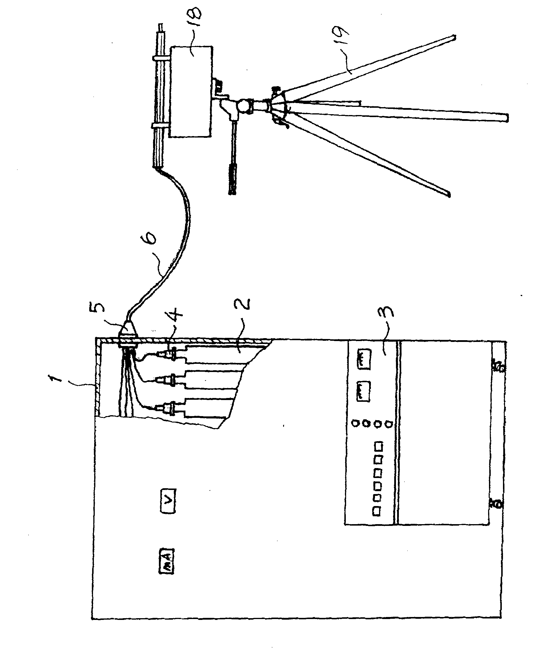
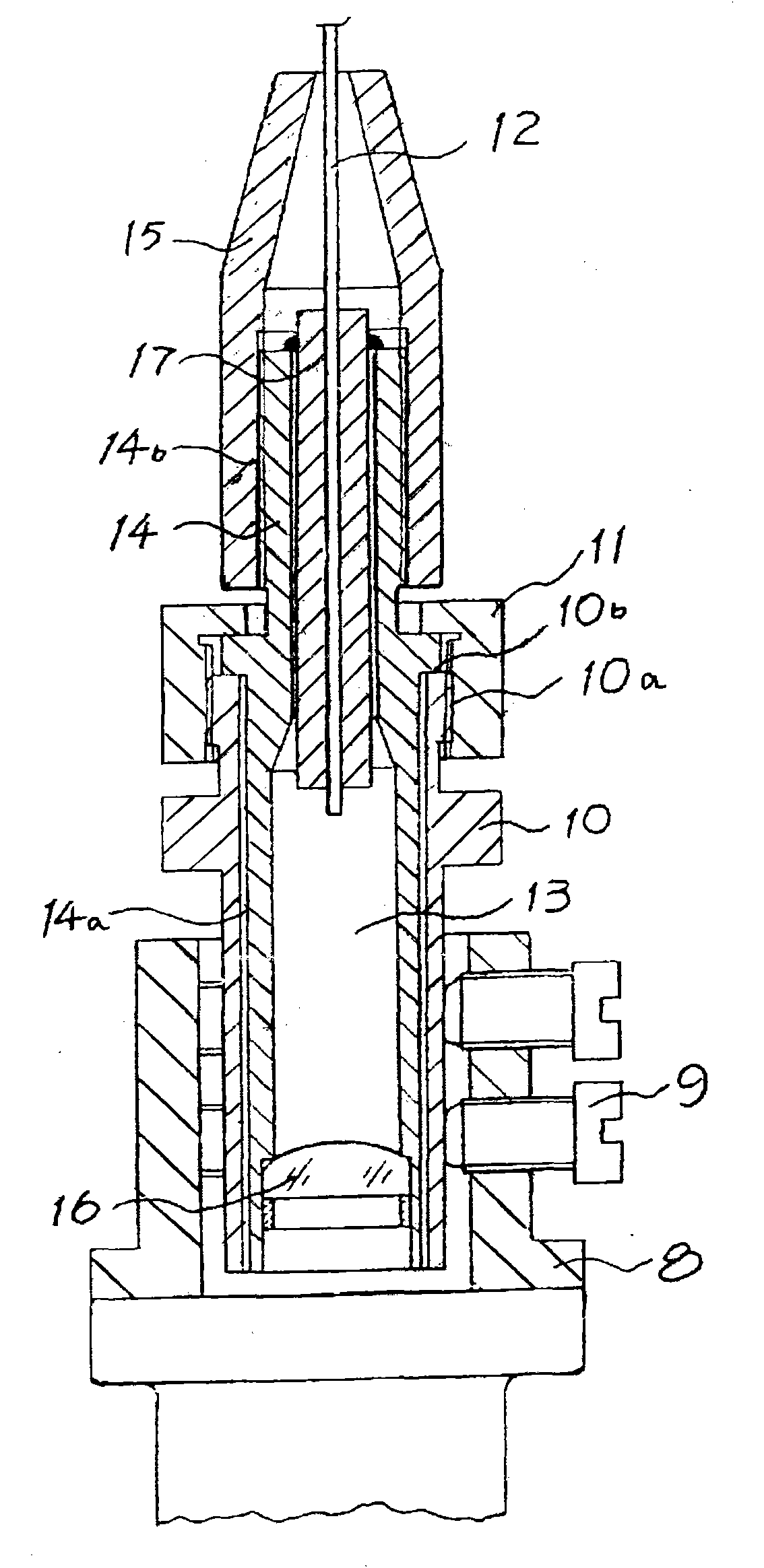
Since the optical fiber 12 is a consumable material, and the input end of the optical fiber 12 is directly screwed into the socket coupling seat 10, it often needs to be replaced, which will easily cause the bolt 9 to loosen, and also cause the seat cover 8 to come into contact with the laser. The bonding of the tube 2 falls off, thereby causing the displacement of the fixing sleeve 17, resulting in a decrease in the coupling efficiency, and even no light output in severe cases. In addition, after the optical fiber 12 is replaced, the coupling needs to be performed again, resulting in a waste of manpower and material resources. low efficiency
In addition, the recoupling mechanism uses a lens sheet to gather multiple bundles of optical fibers into a single bundle of optical fibers, and there is energy loss through the lens sheet, resulting in low coupling efficiency and high cost
Another recoupling mechanism adopts screw adjustment and positioning, which also has the problem of looseness and displacement.

Method used


Image

  • Multi-light guide gain amplification laser equipment
  • Multi-light guide gain amplification laser equipment
  • Multi-light guide gain amplification laser equipment

Examples


Embodiment Construction

[0013] The multi-lightguide gain-amplified laser device provided by the present invention will be described in detail below in conjunction with the accompanying drawings and specific embodiments.

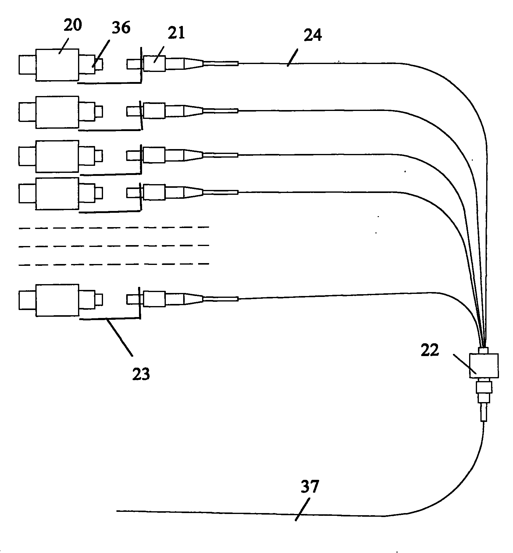
[0014] Such as Figure 3-Figure 5 As shown, the multi-light guide gain amplification laser equipment provided by the present invention includes multiple lasers 36 equipped with laser adjustment devices 20, a plurality of socket-type light-guide coupling devices 21 and socket-type multi-light guide gain amplification devices 22; wherein each laser 36 and a socket-type light guide coupling device 21 are connected to each other by a bracket plate 23; and each socket-type light-guide coupling device 21 is connected to the socket-type multi-light guide gain amplifier 22 through a single optical fiber 24 at the same time.

[0015] The socket-type light guide coupling device 21 includes a socket-type light guide coupler 25, a light guide coupling seat 26, a coupler fixed lock mother 27 and...


PUM


Abstract

The invention relates to multi-light guide gain amplification laser equipment comprising a plurality of laser devices, a plurality of socket type photoconductive coupling devices and a socket type multi-light guide gain amplification device, wherein the laser devices are connected with the socket type multi-light guide gain amplification device by supporting plates; and the socket type photoconductive coupling devices are connected with the socket type multi-light guide gain amplification device by a single optical fiber. The multi-light guide gain amplification laser equipment has a structure that through a photoconductive coupling seat, the socket type photoconductive coupling devices are installed on the supporting plates connected with the laser devices so that once optical fibers on the socket type photoconductive coupling devices need to be replaced, just lock nuts of the coupling devices need to be loosened; and after reinstalled, the socket type photoconductive coupling devices do not need to be adjusted, thereby being convenient for operation, saving labor and time and leading the work efficiency to be high. Besides, by utilizing a positioning fastening device and lock nuts, the socket type multi-light guide gain amplification device leads multiple beam optical fibers to be in direct butt joint with the single beam optical fiber, and any other optical lens are not needed, thereby avoiding energy loss and increasing the coupling efficiency.

Description

technical field [0001] The invention relates to a laser device, in particular to a multi-light guide gain amplification laser device. Background technique [0002] Chinese Invention Patent No. 92103733 discloses a concentrated high-power helium-neon laser therapeutic apparatus that has been applied for by the applicant and has been authorized. figure 1 It is a structural schematic diagram of the concentrated high-power helium-neon laser therapeutic apparatus in the prior art. figure 2 for figure 1 The main cross-sectional view of the coupling mechanism structure in the concentrated high-power He-Ne laser therapeutic apparatus shown. Such as figure 1 As shown, this prior art focused high-power He-Ne laser treatment instrument mainly includes multiple laser tubes 2, multiple coupling mechanisms 4, channel-type fixers 5, recoupling mechanisms and scanning mechanisms not shown in the figure 18; where the output end of each laser tube 2 is glued with a coupling mechanism 4, ...

Claims


Application Information

Patent Timeline
IPC IPC(8): A61N5/067H01S3/23H01S3/091
Inventor 强茹玲汪永一刘宏梅胡英杰岳小文李鹏鸣张旭光
Owner TIANJIN LEIYI LASER TECH
Learn More