
Humanoid robot head based on bevel gear differential coupling mechanism

A technology of humanoid robot and coupling mechanism, which is applied in manipulators, program-controlled manipulators, manufacturing tools, etc., can solve the problems of large head space, large independent joint structure, and uncompact head structure, etc., and achieve large internal space, Improving the effect of humanoid and compact structure

Inactive Publication Date: 2010-09-22
HARBIN INST OF TECH
View PDF0 Cites 37 Cited by
  • Summary
  • Abstract
  • Description
  • Claims
  • Application Information

AI Technical Summary

Problems solved by technology

[0004] In order to solve the problem that the head structure of the existing humanoid robot is not compact, the volume of the independent joint structure is large, the head occupies a large space, and only has two motions of pitching and turning, the present invention further provides a bevel gear-based Humanoid Robot Head with Differential Coupling Mechanism

Method used


Image

  • Humanoid robot head based on bevel gear differential coupling mechanism
  • Humanoid robot head based on bevel gear differential coupling mechanism
  • Humanoid robot head based on bevel gear differential coupling mechanism

Examples


specific Embodiment approach 1

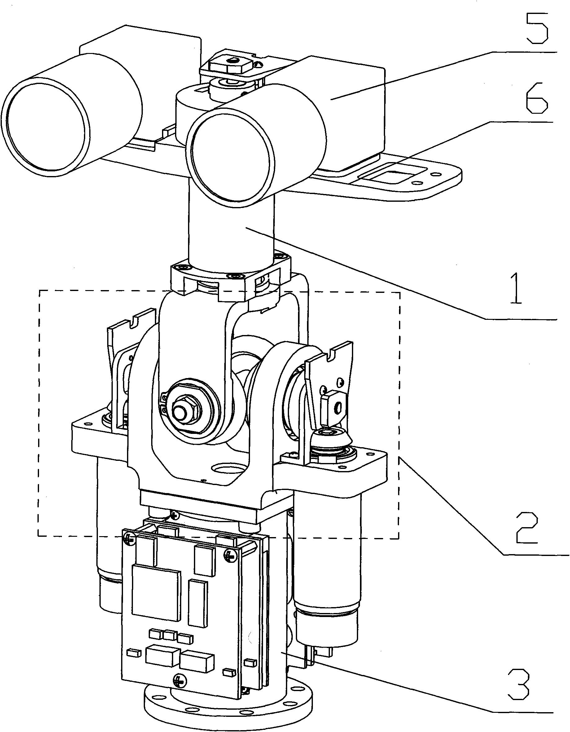
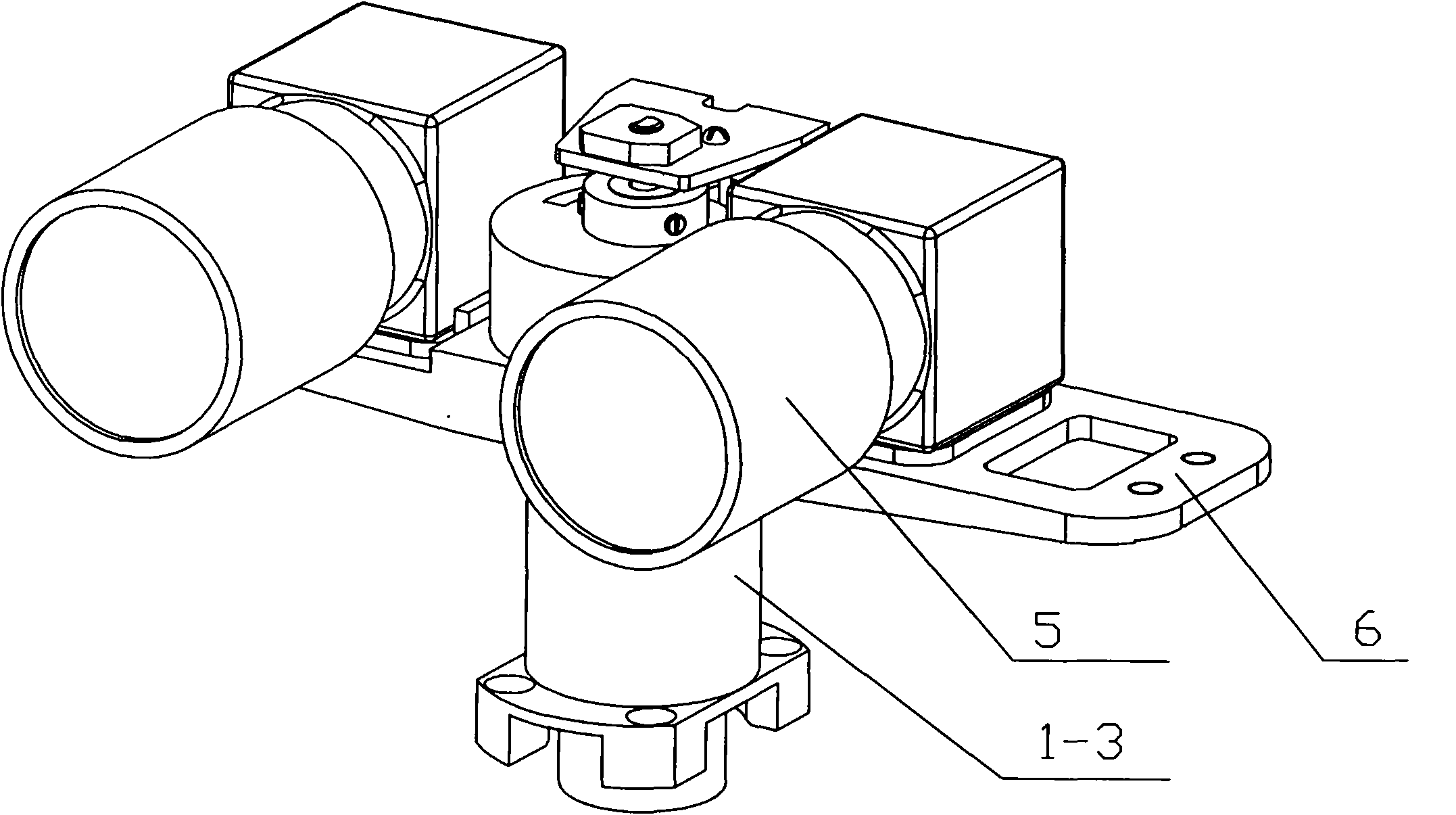
[0010] Specific implementation manner one: such as Figure 1-9 As shown, the head of the humanoid robot of this embodiment is composed of a head revolving joint 1, a neck base joint 2, a neck base 3, a head shell 4, two cameras 5, and two camera mounting adjustment slides 6. The head rotary joint 1 is composed of the first disc brushless DC motor 1-1, planetary gear reducer 1-2, rotary joint support 1-3, camera rotary bracket 1-4, rotary hollow sleeve shaft 1-5, The deep groove ball bearing 1-6 and the joint angle feedback shaft 1-7 are formed, the output end of the first disc brushless DC motor 1-1 is drivingly connected with the input end of the planetary gear reducer 1-2, and the planet The gear reducer 1-2 is installed in the inner hole of the rotary joint support 1-3, and the output shaft of the planetary gear reducer 1-2 is fixedly installed in the inner hole of the rotary hollow sleeve shaft 1-5. The hollow sleeve shaft 1-5 (through the set screw 1-10) is installed in t...

specific Embodiment approach 2

[0014] Specific implementation manner two: such as figure 1 As shown, the head shell 4 of this embodiment is made of resin plastic (made by rapid prototyping), which is easy to process. Other components and connection relationships are the same as those in the first embodiment.

specific Embodiment approach 3

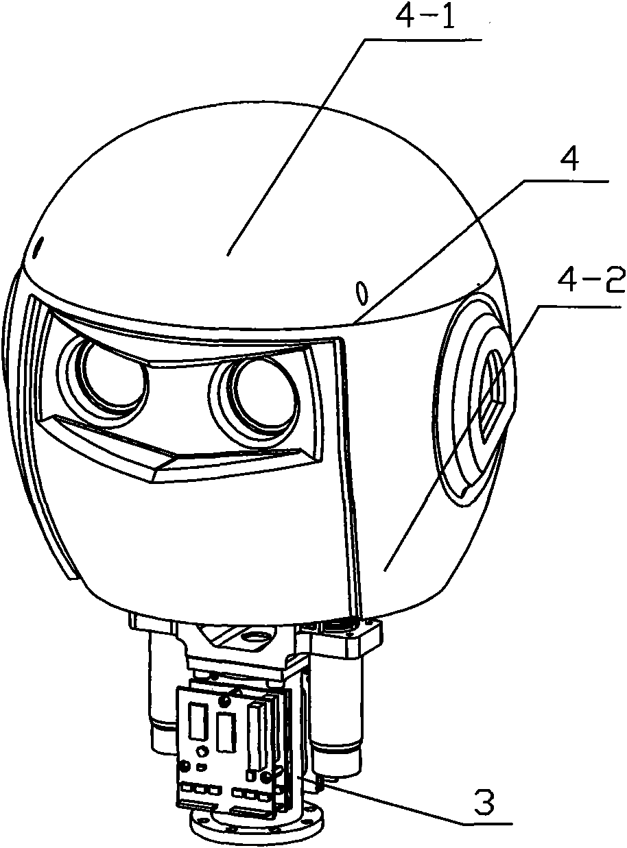
[0015] Specific implementation manner three: such as figure 1 As shown, the head shell 4 of this embodiment is composed of an upper head shell 4-1 and a lower head shell 4-2, and the lower head shell 4-2 is detachably connected to the upper head shell 4-1. This structure is easy to disassemble and install. Other components and connection relationships are the same as those in the first or second embodiment.


PUM


Abstract

The invention relates to a humanoid robot head based on a bevel gear differential coupling mechanism which relates to a humanoid robot head. The invention solves the problems that the structure of the existing head is not compact, the volumes of independent joints are larger and occupy more space of the head and the head only has two motion ways of pitching and turning round. The turning joint of the head is connected with the motion output support of a neck base joint through a turning joint supporting seat; the neck base joint is connected with a neck seat in a neck base through a neck base joint supporting seat; the shell of the head is fixedly connected with a camera turning support; a free differential bevel gear is separately meshed with two driving differential bevel gears, a driven differential bevel gear is separately meshed with the two driving differential bevel gears; and the gear tooth parameters of the two driving differential bevel gears, the driven differential bevel gear and the free differential bevel gear are consistent, and all the gears constitute the differential bevel gear mechanism. The invention is used in the vision measurement and tracking of the humanoid robot head.

Description

Technical field [0001] The invention relates to a robot head. Background technique [0002] Humanoid robots are currently a research hotspot in the field of robotics. As an important part of the humanoid robot, the head of the humanoid robot is to imitate the movement of the human head, and is equipped with cameras and other sensors to realize visual measurement and control. At the same time, it should have a humanoid appearance to realize the human-computer interaction. And sex. [0003] The existing humanoid robot head generally separates the control system and the structural body into a separate control box or box, so the volume is large, the independent joint structure has a large volume, takes up a large space in the head, and is used more frequently The head of the humanoid robot with independent joints only has two movements, namely, pitch and rotation. Summary of the invention [0004] In order to solve the problem of the existing humanoid robot head structure is not comp...

Claims


Application Information

Patent Timeline
IPC IPC(8): B25J19/00
CPCB25J9/102
Inventor 刘宏王滨朱俊杰刘伊威孙奎周扬
Owner HARBIN INST OF TECH
Learn More