
Servo puffing and direct-blowing mechanism

A technology of blowing mechanism and servo motor, applied in the direction of blowing head, etc., can solve the problems of high operating level requirements of operators, poor working environment, poor labor intensity, unstable work of the mechanism, etc., to improve operability and safety, Institutional response is intuitive and the effect of reducing energy consumption

Inactive Publication Date: 2010-09-22
SHANDONG SANJIN GLASS MASCH CO LTD
View PDF3 Cites 2 Cited by
  • Summary
  • Abstract
  • Description
  • Claims
  • Application Information

AI Technical Summary

Problems solved by technology

With the wear of the upper and lower bushings of the piston rod, the leakage of compressed air will cause waste of energy, and at the same time cause the mechanism to work unstable; the mechanism is installed on the frame plane to provide the pipeline installation of compressed air for the up and down movement of the piston Inside the frame, it is controlled by the valve box, and the frame is closed. If the pipeline leaks or is blocked, the operation of the mechanism is unstable, because the internal pipeline is relatively complicated, it will bring certain difficulties to the maintenance of the mechanism; in addition, when the mechanism is working , the adjustment of the rising and falling speed and the buffer is controlled by the valve needle, which requires a high level of operation for the operator, and the working environment and labor intensity are relatively harsh.

Method used


Image

  • Servo puffing and direct-blowing mechanism
  • Servo puffing and direct-blowing mechanism
  • Servo puffing and direct-blowing mechanism

Examples


Embodiment Construction

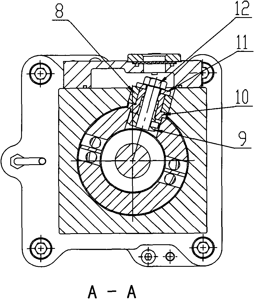
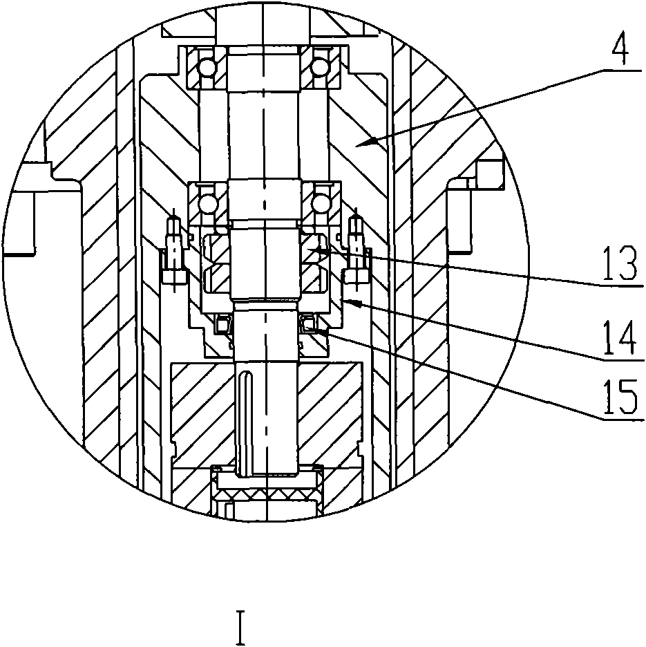
[0016] Attached below Figure 1-7 The servo puffing and positive blowing mechanism of the present invention will be further described in detail:

[0017] refer to Figure 1-7 :

[0018] The servo blowing and forward blowing mechanism is installed in a vertical hole on the frame and fixed on the frame. The bottle making machine is generally composed of multiple frames with working mechanisms installed side by side. Each frame assembly is individually Work, and finally transport the product to the bottle conveyor. The whole machine is controlled by an electronic timing system, so that each frame does not interfere with each other, that is to say, the products transported to the bottle conveyor will not collide and have the same spacing. In the servo blowing mechanism, the main shaft 6 moves up and down reciprocatingly. When the main shaft 6 descends, it carries the blowing arm and falls to the correct position above the mould, so as to perform the blowing process. After the w...


PUM


Abstract

The invention relates to a servo puffing and direct-blowing mechanism, belonging to the field of glass machinery. The mechanism comprises a servo motor (1), a base (2), a coupler (3), a bearing block (4), a ball screw pair (5), a main shaft (6), a cam (7) and a cam roller assembly, wherein the upper part of the base (2) is connected with the lower part of the cam (7), the bearing block (4) and the coupler (3) are installed in the hollow base (2), the main shaft (6) is hollow, the ball screw pair (5) is installed in the central cavity of the main shaft (6), the cam (7) is a rectangular hollow body, the main shaft (6) is installed in a central round hole, the front surface of the cam (7) is provided with a cam slot, and the cam roller of the cam roller assembly is installed in the cam slot. The mechanism is operated by being driven by the rotation of the servo motor instead of compress air to drive the piston, thereby lowering energy consumption, reducing noise, improving the operability and safety of the mechanism and decreasing maintenance complexity.

Description

technical field [0001] The utility model relates to a servo blowing and forward blowing mechanism, which belongs to the field of glass machinery. The servo blowing mechanism and the servo positive blowing mechanism are two mechanisms of the full servo bottle making machine. Their structure and movement principle are basically the same, but because of the different functions, the installation position and installation height are slightly different. The following is The servo puff mechanism is taken as an example for illustration. Background technique [0002] Glass bottle machinery industry technology has developed rapidly in recent years. The application of mechatronics technology has brought many advantages to the development of bottle making machines. It is convenient for users to operate and maintain, and the timing is accurate and the function is reliable. The application provides a good platform. Bottle-making machinery has the disadvantage of high energy consumption....

Claims


Application Information

Patent Timeline
IPC IPC(8): C03B9/36
Inventor 李绪刚孙健雷维婷李玉鹏
Owner SHANDONG SANJIN GLASS MASCH CO LTD
Learn More