Internal combustion type rail belt grinder

A grinding machine and rail technology, which is applied to the field of internal combustion type steel rail abrasive belt grinding machines, can solve the problems that it is difficult to meet the requirements of short-time skylight operation, the external size of the grinding wheel grinding machine is large, and the grinding wheel rotation speed cannot be too high, etc., and achieves light weight and compact structure. , Simple effect of grinding adjustment mechanism

Inactive Publication Date: 2010-09-22
李洪彬
View PDF7 Cites 17 Cited by
  • Summary
  • Abstract
  • Description
  • Claims
  • Application Information

AI Technical Summary

Problems solved by technology

In the traditional welding seam grinding operation, grinding wheel grinding machines are often used for grinding rail welds. The grinding wheel grinding machine has large dimensions, heavy equipment, complex structure, high operating intensity, and inconvenient maintenance. At the same time, the grinding wheel grinding machine uses grinding wheel grinding. The grinding wheel and rail Rigid contact, large vibration, and the speed of the grinding wheel should not be too high, so the grinding efficiency of the grinding wheel is low, and it is difficult to meet the requirements of short-term skylight operations; at the same time, because the contact area between the grinding wheel and the weld is small, the grinding wheel wears quickly, and the height of the grinding wheel must be adjusted continuously during the grinding process. The operator is labor intensive

Method used


Image

  • Internal combustion type rail belt grinder
  • Internal combustion type rail belt grinder
  • Internal combustion type rail belt grinder

Examples


Embodiment Construction

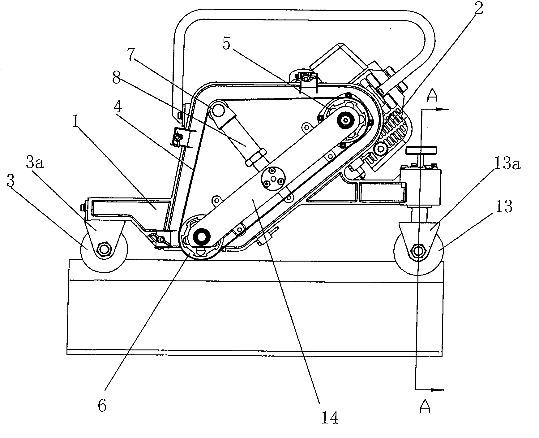
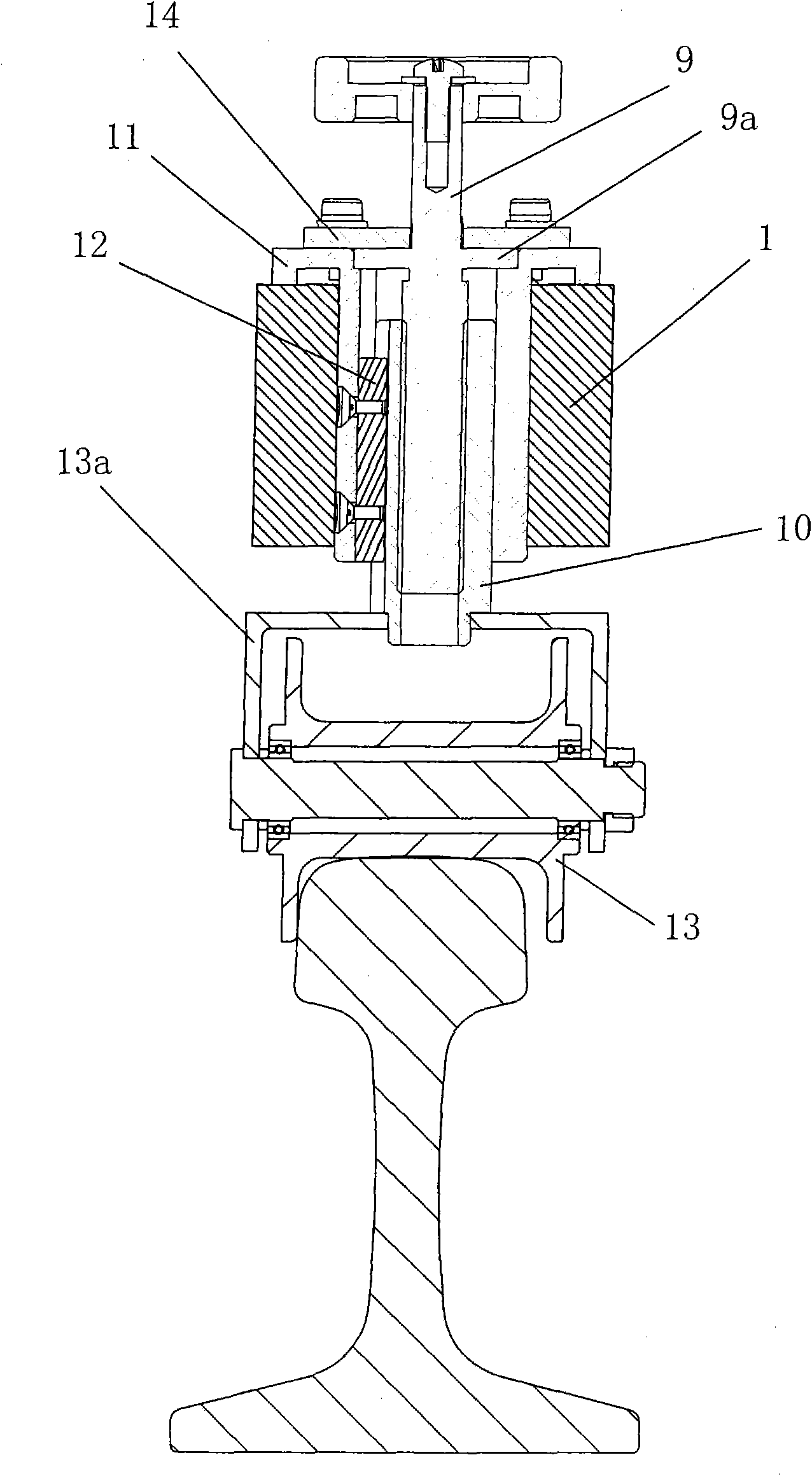
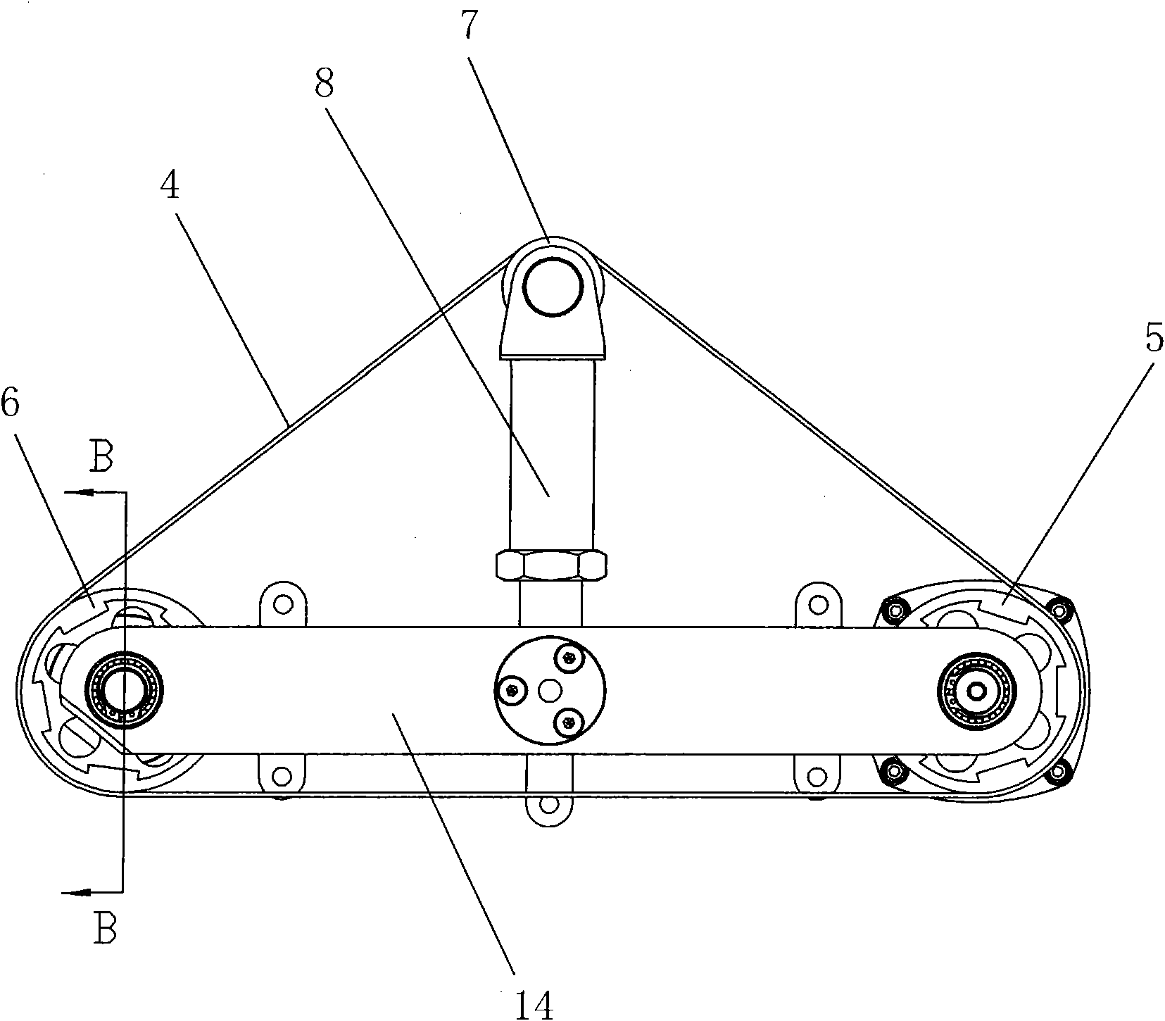
[0015] figure 1 It is a schematic diagram of the overall structure of the internal combustion type rail abrasive belt grinding machine of the present invention; figure 2 for figure 1 Sectional view along A-A; image 3 It is a schematic diagram of the abrasive belt drive structure of the internal combustion type rail abrasive belt grinder of the present invention; Figure 4 for image 3 Sectional view along B-B.

[0016] As shown in the figure, the internal combustion rail abrasive belt grinding machine of the present invention includes a frame 1, an abrasive belt 4, a driving wheel 5, a contact wheel 6, a tensioning wheel 7, a front walking profiling wheel 3 arranged on the frame 1 and Back walking profiling wheel 13 and the internal combustion engine 2 that is arranged on frame 1 and is used to drive drive wheel 5 to rotate, described emery belt 4 is wound on the outer circle of drive wheel 5, contact wheel 6 and tension wheel 7 successively, An adjusting mechanism for ...


PUM


Abstract

The invention discloses an internal combustion type rail belt grinder, comprises a rack, a sanding belt, a driving wheel, a contact wheel, a tension pulley, a front travel contour wheel, a rear travel contour wheel and an explosive motor, wherein the front travel contour wheel and the rear travel contour wheel are arranged on the rack; the explosive motor is arranged on the rack and drives the driving wheel to rotate; the sanding belt is orderly wound on the excircles of the driving wheel, the contact wheel and the tension wheel; and a regulation mechanism for regulating the height of the rack is arranged between the rack and the front travel contour wheel or between the rack and the rear travel contour wheel. In the invention, the sanding belt is adopted to grind; the excircle of the contact wheel pressing the sanding belt on a welding line is provided with annular rubbers; the sanding belt is contacted with the welding line in a flexible mode, and the contact area is large, and the grinding efficiency is high; the variation in sanding belt thickness is small during grinding, thus the regulating operation of the grinding height is less, and the work efficiency is high; the regulation mechanism of the invention is simple, and the regulation is convenient and reliable; the driving wheel, the contact wheel and the tension wheel are all arranged on the support plate and the mounting and the debugging are convenient; and the explosive motor is suitable for field electroless operation.

Description

technical field [0001] The invention relates to a grinder, in particular to an internal combustion type steel rail abrasive belt grinder. Background technique [0002] After on-line welding and welding repair of railway rails, the weld seams need to be polished to make the surface of the rails smooth. In the traditional welding seam grinding operation, grinding wheel grinding machines are often used for grinding rail welds. The grinding wheel grinding machine has large dimensions, heavy equipment, complex structure, high operating intensity, and inconvenient maintenance. At the same time, the grinding wheel grinding machine uses grinding wheel grinding. The grinding wheel and rail Rigid contact, large vibration, and the speed of the grinding wheel should not be too high, so the grinding efficiency of the grinding wheel is low, and it is difficult to meet the requirements of short-term skylight operations; at the same time, because the contact area between the grinding wheel ...

Claims


Application Information

Patent Timeline
Patent Type & Authority Applications(China)
IPC IPC(8): E01B31/17
Inventor 李洪彬
Owner 李洪彬
Why Eureka
Try Eureka