Ball valve

A ball valve and ball gasket technology, applied in valve details, valve device, valve shell structure, etc., can solve the problems of high processing and assembly requirements, hidden leakage, low processing efficiency, etc., to reduce processing and assembly requirements, and adjust sealing performance. , the effect of energy saving and processing efficiency

Inactive Publication Date: 2012-01-04
宁波日月制冷设备有限公司
View PDF0 Cites 0 Cited by
  • Summary
  • Abstract
  • Description
  • Claims
  • Application Information

AI Technical Summary

Problems solved by technology

[0004] 1. Since the main body of the ball valve and the end cover are threaded, there is a fit tolerance between the two. Some of them use an external gasket structure, but there is a hidden danger of leakage; while the overall welding has seams, so the strength is not enough, and there may be leakage, that is, two leak-proof performance is poor
[0005] 2. Since the main body of the ball valve is all made of brass through cutting and other mechanical processing, the material is wasteful and the processing efficiency is low; while casting processing is used, the mold cost is high, and defects such as trachoma and slag inclusion are prone to occur, and the processing efficiency is low and the cost is expensive.
[0006] 3. Due to the high temperature generated during the overall welding may affect the parts installed in the main body of the ball valve, it is easy to deform or damage the internal parts and cause the seal to fail
[0007] 4. Due to the fit gap between the main body of the ball valve and the internal parts, in order to make the ball valve have a good seal, the processing and assembly requirements for the parts are very high, which also makes the cost high; Adjust the gap between the main bodies of the ball valve, but the adjustment range is not much, the effect is not good, and there may be leakage

Method used


Image

  • Ball valve
  • Ball valve
  • Ball valve

Examples


Embodiment Construction

[0022] The present invention will be further described below in conjunction with the accompanying drawings and specific embodiments.

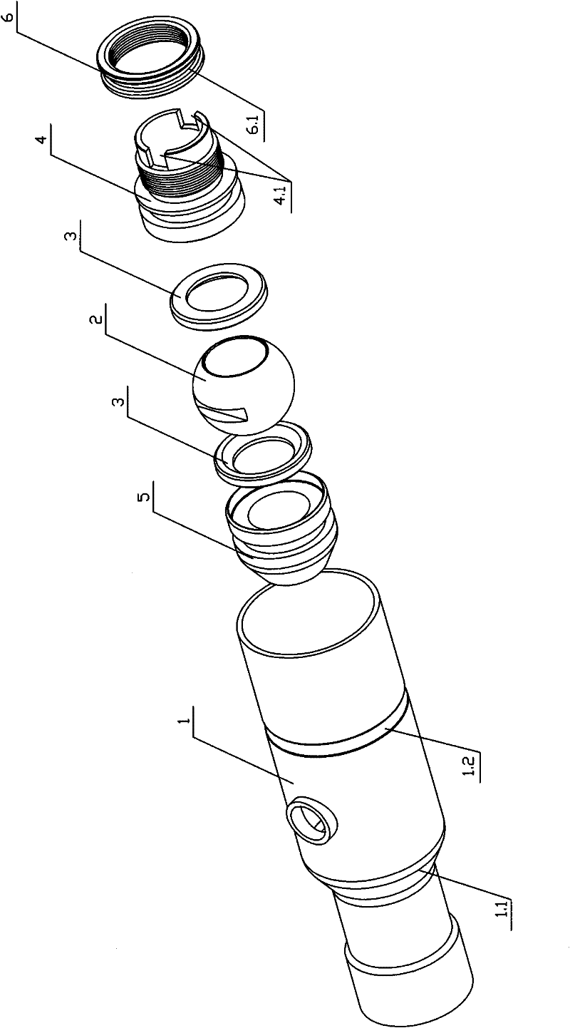
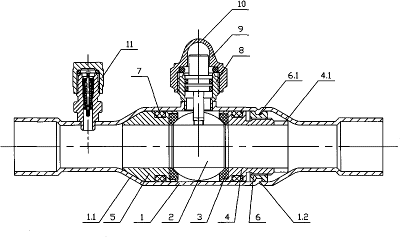
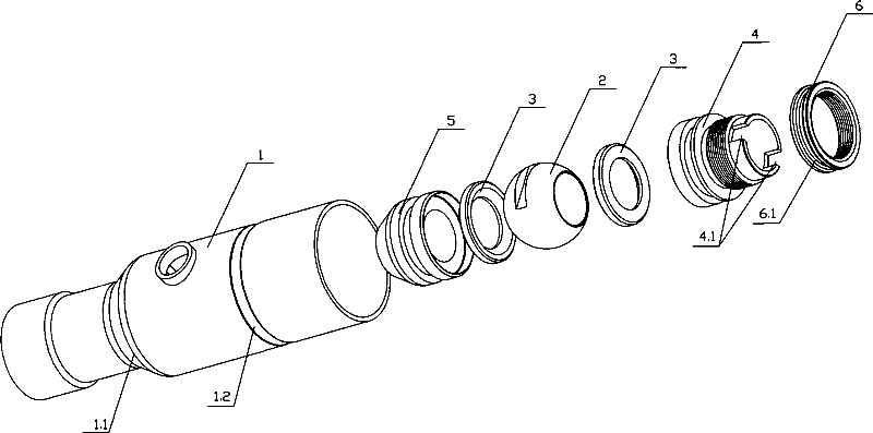
[0023] Such as figure 1 , figure 2 As shown, the ball valve of the present invention includes a ball valve body 1, a ball 2, two ball pads 3, a first inner plug body 4, and a second inner plug body 5; the ball 2 is positioned on the ball valve body by the ball pads 3 on both sides. In the inner cavity of the main body 1, one end of the first inner plug body 4 and the second inner plug body 5 are all against the corresponding ball cushion 3, and the first inner plug body 4 and the second inner plug body 5 are connected to the ball valve main body 1 Sealing between the first inner plug body 4 and the second inner plug body 5 and the ball valve body 1 is provided with a sealing ring 7; the liquid filling assembly 11 and the top connecting body 8 are welded on the ball valve body 1 Above, the valve stem assembly 9 is arranged in the top connecti...


PUM


Abstract

The invention discloses a ball valve comprising a ball valve main body (1), a ball (2), two ball cushions (3), a first inner plugging body (4) and a second inner plugging body (5), wherein the ball valve main body (1) is an integrated whole and is provided with two throats (1.1) capable of limiting the corresponding inner plugging bodies in the ball valve main body (1); the other end of the firstinner plugging body (4) and the other end of the second inner plugging body (5) are both abutted on the inner wall of the throats (1.1) of the ball valve main body (1); and an actuating device capable of adjusting tightness is arranged between one of the first inner plugging body (4) and the second inner plugging body (5) and the ball valve main body (1). The ball valve has favorable leakage-proof performance, material saving, high processing efficiency and low cost, does not affect internal parts when being assembled and does not leak when being adjusted.

Description

technical field [0001] The invention relates to a valve, in particular to a ball valve. Background technique [0002] The ball valve is when the ball rotates 90 degrees, all the spherical surfaces are presented at the inlet and outlet, so as to cut off the flow. Because the ball valve only needs to be operated by rotating 90 degrees and a small rotational torque to close tightly, and the fully opened valve inner cavity provides a straight-through flow channel with little resistance for the medium, which is suitable for direct opening and closing, and can also be used Used for throttling and controlling flow. Especially its compact structure, easy operation and maintenance, suitable for water, solvent, acid and natural gas working medium. [0003] The current ball valve structure generally includes a ball valve body, a ball, two ball pads, an end connector, a cap, a top connector, a valve stem assembly, and a liquid filling assembly; the ball is positioned in the inner cavi...

Claims


Application Information

Patent Timeline
Patent Type & Authority Patents(China)
IPC IPC(8): F16K5/06F16K5/20F16K27/06
Inventor 陈明均
Owner 宁波日月制冷设备有限公司
Why Eureka
Try Eureka