Satellite image system error correction method based on bias matrix with time factor

A technology of satellite imagery and offset matrix, applied in the field of surveying and mapping science

Inactive Publication Date: 2010-09-22
WUHAN UNIV
View PDF5 Cites 13 Cited by
  • Summary
  • Abstract
  • Description
  • Claims
  • Application Information

AI Technical Summary

Problems solved by technology

Since the conventional system error correction model based on bias matrix or generalized bias matr

Method used


Image

  • Satellite image system error correction method based on bias matrix with time factor
  • Satellite image system error correction method based on bias matrix with time factor
  • Satellite image system error correction method based on bias matrix with time factor

Examples


Embodiment

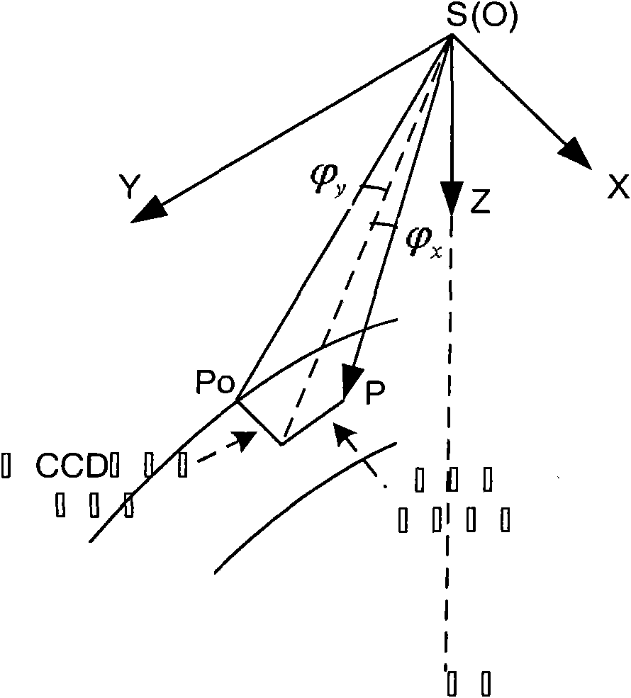
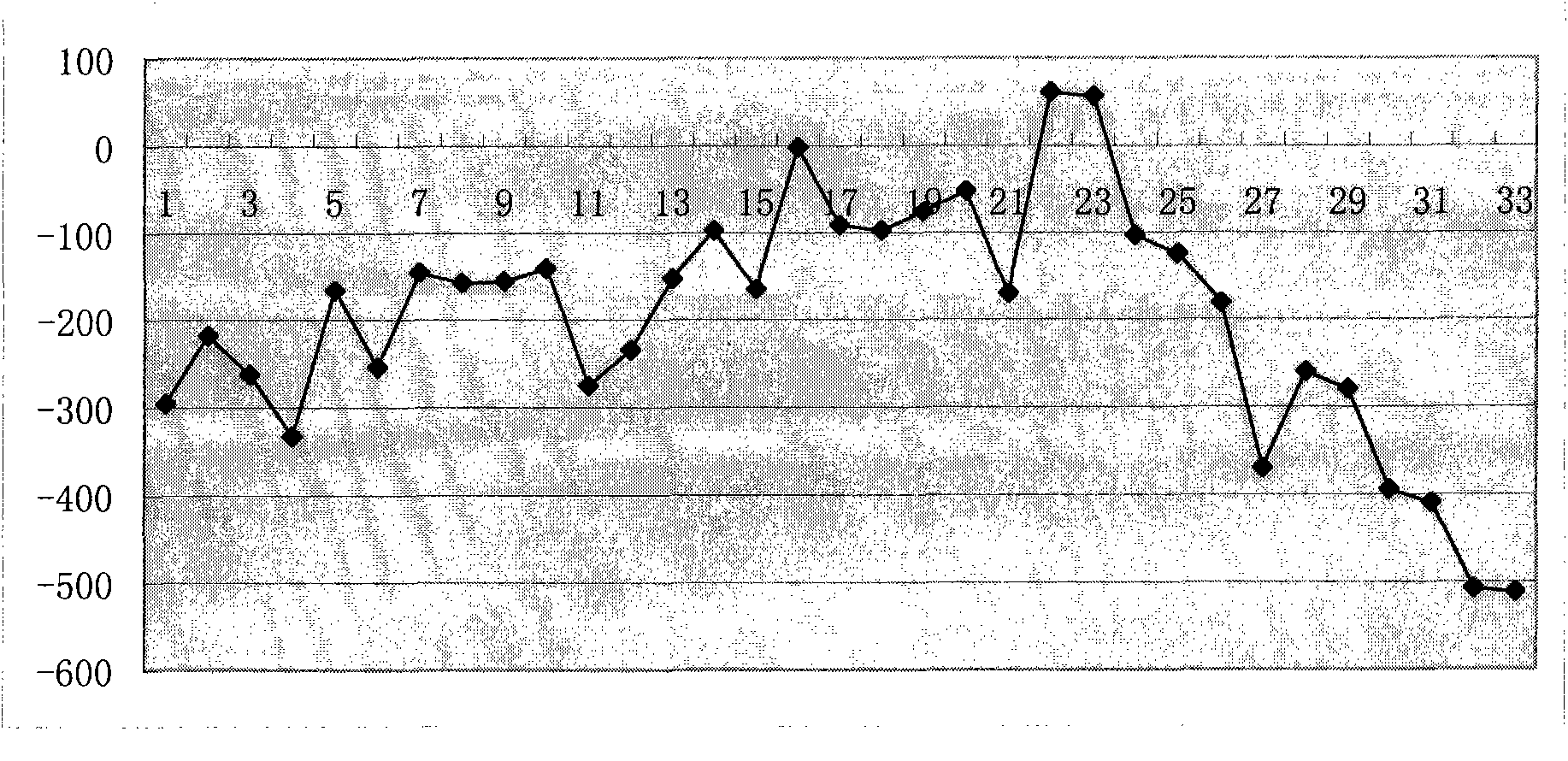
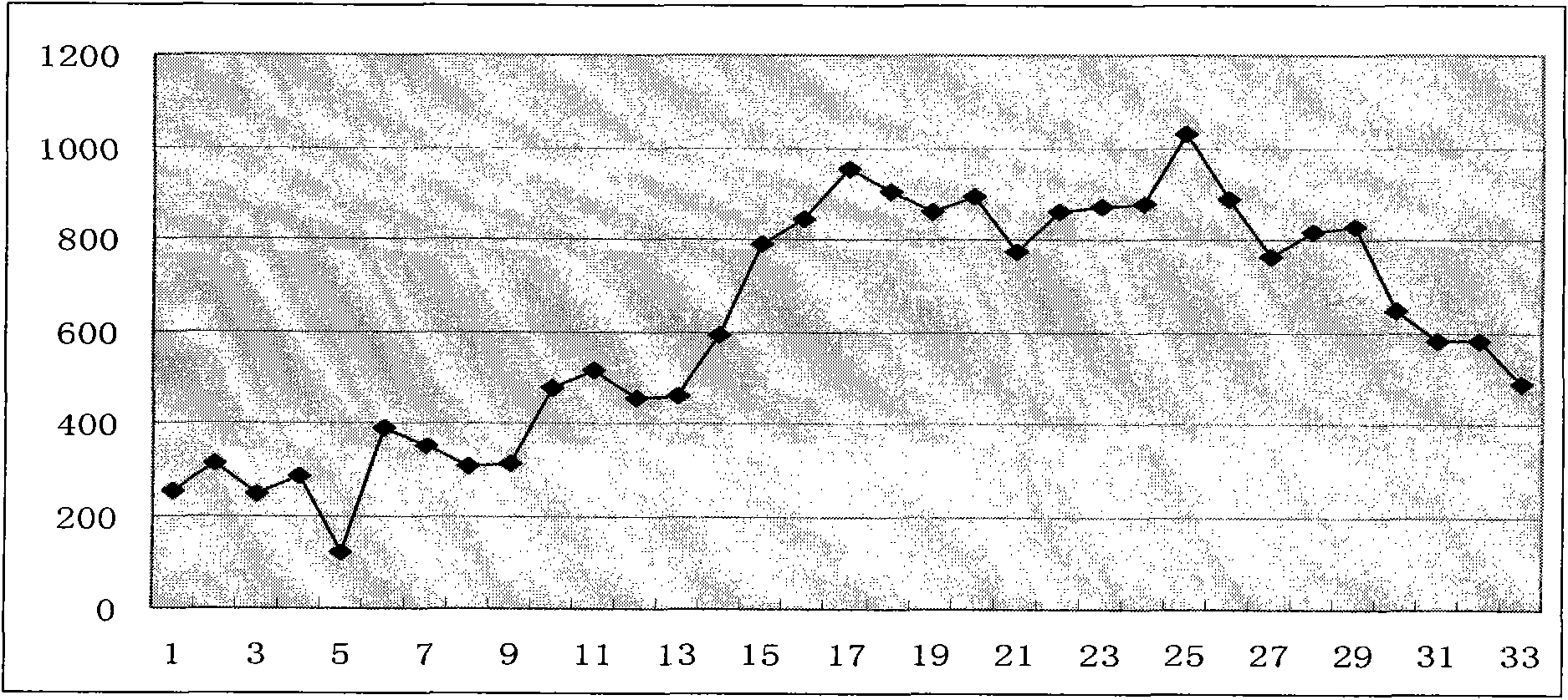
[0061] Example: Take a total of 33 sample image data acquired within 9 consecutive months (the imaging time of the 33 sample images is different, and they are distributed as evenly as possible within the 9 consecutive months), and the images cover Beijing, Hebei , Zhejiang, Hubei, Shandong and other provinces and cities. Several checkpoints were measured on each image, and the checkpoints were roughly evenly distributed on each image. Check the size and direction of the positioning error of the checkpoint on each scene image: Regardless of the camera placement error, the collinear condition equation is directly constructed based on the auxiliary data such as the original orbit, attitude, and initial installation angle of the camera, and the calculation point along the CCD in each scene is calculated. The positioning error in the direction and along the track direction, draw the positioning error map of each scene image in the two directions. Such as figure 2 and image 3 A...


PUM


Abstract

The invention relates to a satellite image system error correction method based on bias matrix with a time factor. The problem of system error correction comes down to the solution of two bias angles of a camera going around a satellite body, aiming at linear variation rules of the geometric positioning error of an image in a certain in-orbit testing period, a first order polynomial with the time factor is used for expressing the bias angles, the first order polynomial is solved based on the selected sample images and the error compensation of a plurality of automatically extracted control points, and thereby the bias matrix of any satellite images in the period is obtained and is substituted in a co-linearity condition equation to realize the effective compensation and the correction of the geometric positioning system error. According to the in-orbit testing results, the method is simple and feasible, the system errors changing with time can be effectively eliminated and the long-term stability of the precision of the system geometrically corrected product is kept.

Description

technical field [0001] The invention belongs to the field of surveying and mapping science and technology, and relates to a satellite image system error correction method based on an offset matrix with a time factor. Background technique [0002] In recent years, my country has successively launched a number of high-resolution optical remote sensing satellites, providing a large amount of data for scientific experiments, land and resources census, crop yield estimation, disaster prevention and mitigation, and other fields, playing an important role in the development of my country's national economy. Panchromatic CCD cameras are important imaging payloads for high-resolution satellites. They are generally rigidly connected to stars and imaged using linear array push-broom methods. After the satellite is in orbit, the related performance test of the ground application system of the satellite is carried out, so as to provide a basis for the adjustment of the payload parameters...

Claims


Application Information

Patent Timeline
IPC IPC(8): G01C11/04
Inventor 王密金淑英胡芬
Owner WUHAN UNIV
Why Eureka
Try Eureka