Ceramic thyratron

A technology of thyratron and ceramics, which is applied in the field of thyratron, can solve problems such as long-term stable work and difficulty in universal replacement, and achieve the effects of ensuring conduction and heat dissipation capabilities, excellent heat dissipation performance, and stable work

Active Publication Date: 2010-09-22
KUNSHAN GUOLI VACUUM ELECTRIC
View PDF0 Cites 3 Cited by
  • Summary
  • Abstract
  • Description
  • Claims
  • Application Information

AI Technical Summary

Problems solved by technology

Ordinary ceramic thyratrons cannot work stably for a long time without wind cooling, which brings difficulty in universal replacement for some equipment without fan cooling

Method used


Image

  • Ceramic thyratron
  • Ceramic thyratron
  • Ceramic thyratron

Examples


Embodiment

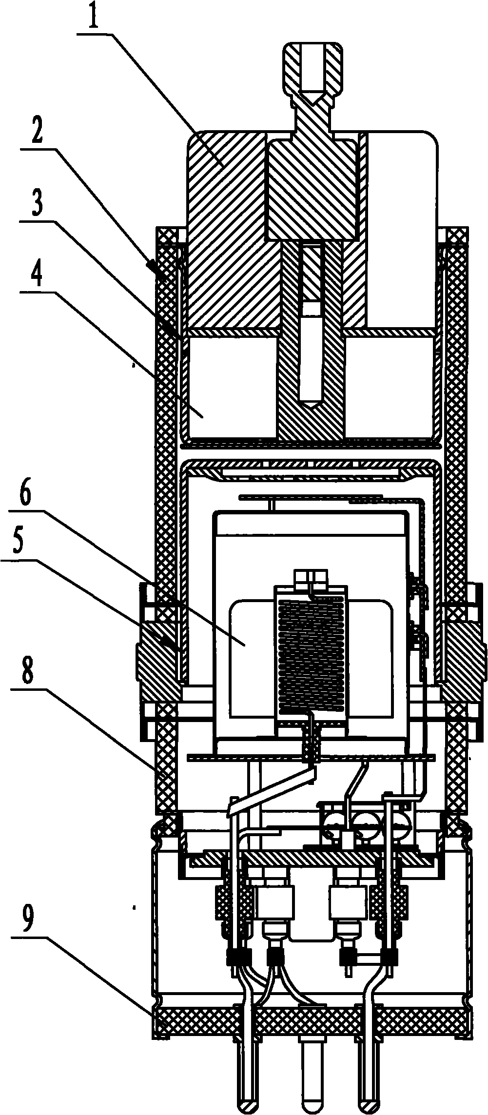
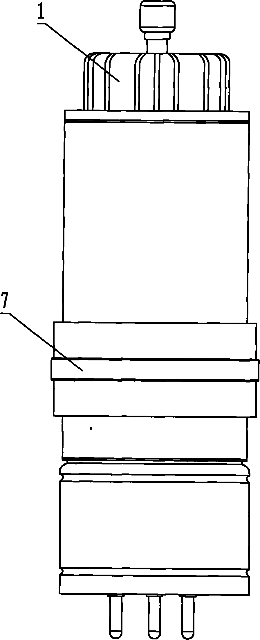
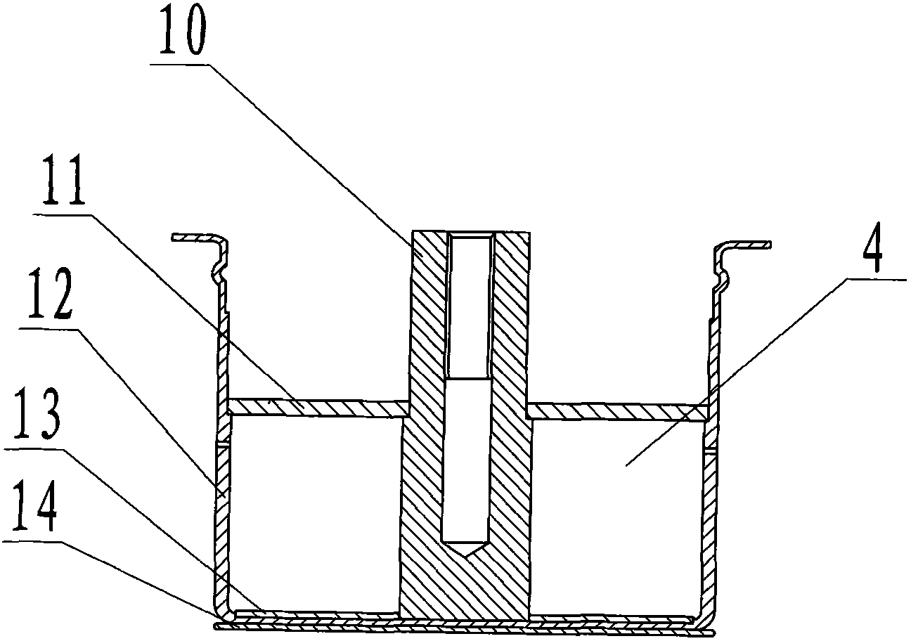
[0020] Embodiment: A ceramic thyratron, including an anode part 3, a grid part 5 and a cathode part 6, the grid part 5 is composed of a grid baffle 18, a grid cup 19 and a control grid lead 21, the grid baffle The plate 18 is fixedly placed on the bottom of the grid cup 19, and the control grid lead wire 21 is fixedly connected to the cup mouth of the grid cup 19. Based on the assembly direction: the lower part of the anode ceramic seal 2 is fixedly connected to the grid part 5, and the grid part 5 is fixed to the bottom of the grid. The pole part 5 is fixedly connected to the upper part of the cathode grid part 8, the position of the tube base part 9 is fixed below the cathode part 8, the position of the cathode part 6 is fixed between the grid part 5 and the tube base part 9, and the anode part 3 is fixedly positioned on the anode On the porcelain seal 2; the anode part 3 includes a molybdenum anode 14, a lining plate 13, an anode cup 12, an anode plate 11 and an anode lead 1...


PUM


Abstract

The invention discloses a ceramic thyratron. In the thyratron, a grid part is fixedly connected with the lower part of an anode ceramic seal part, and is fixedly connected with the upper part of a cathode grid part; the position of a tube base part is fixed under the cathode grid part; the position of the cathode part is fixed between the grid part and the tube base part; and the anode part is fixedly positioned on the anode ceramic seal part. The anode part comprises a molybdenum anode, a lining plate, an anode cup, an anode plate and an anode lead wire, wherein the anode cup is fixed on the molybdenum anode; the lining plate is fixed on the bottom of the interior of the anode cup; one end of the anode lead wire is fixedly arranged at the central hole of the lining plate in a penetrating manner; the anode plate is fixedly sleeved in the middle of the anode lead wire; a circle of through holes are uniformly provided at the middle of the wall of the anode cup; the anode plate can just seal the upper parts of the through holes, thus an anode hydrogen storage cavity is separated in the inner space of the anode cup for gas ionization supplying for anode-grid space; and a grid radiating ring is fixedly sleeved on the outer wall of the mouth of the grid cup, so that the heat dissipation performance of the grid part can be improved, and the whole tube temperature of the ceramic thyratron can be reduced.

Description

technical field [0001] The invention relates to a thyratron, in particular to a ceramic thyratron. Background technique [0002] At present, the known thyratron structure is mainly composed of an anode, a control grid, a cathode, a cathode filament and a heating part of a hydrogen storage device, and some thyratrons also have an auxiliary grid. Connect each part of the thyristor to the corresponding power line of the equipment, first apply voltage to the cathode filament and hydrogen storage device to preheat, and at the same time apply power supply voltage to the auxiliary grid and control grid, when the preheating time is over, It can work by adding high voltage to the anode. While applying high voltage to the anode, the ceramic thyristor must use a fan to cool the anode or cathode of the ceramic thyristor with forced air, and it is best to cool the anode and cathode at the same time. Ordinary ceramic thyratrons cannot work stably for a long time without wind cooling, wh...

Claims


Application Information

Patent Timeline
Patent Type & Authority Applications(China)
IPC IPC(8): H01J17/00
Inventor 李宗超黄俊杰黄浩曹鸣坤
Owner KUNSHAN GUOLI VACUUM ELECTRIC
Why Eureka
Try Eureka