
Organic electroluminescent diode apparatus

An electroluminescent layer, electroluminescent technology, applied in the direction of electric solid devices, electrical components, semiconductor devices, etc., can solve the problems of ITO thin film morphology, carrier transport and injection performance difficult to control, and organic electroluminescent device reliability. Guarantee, unstable performance of organic electroluminescent devices, etc., to achieve excellent carrier transport and injection performance, avoid rapid aging, and reliable performance.

Inactive Publication Date: 2010-09-22
苏璇
View PDF3 Cites 11 Cited by
  • Summary
  • Abstract
  • Description
  • Claims
  • Application Information

AI Technical Summary

Problems solved by technology

[0004] However, ITO as an anode has many insurmountable deficiencies in the application of organic electroluminescent devices: first, in the process of preparing ITO thin films, the proportion composition of elements indium (In) and tin (Sn) is not suitable for control, so ITO thin films It is difficult to control the morphology, carrier transport and injection properties of organic electroluminescent devices, which makes the performance of organic electroluminescent devices unstable
It can be seen that this anode alternative has no cost advantage, and the reliability of organic electroluminescent devices is difficult to guarantee

Method used


Image

  • Organic electroluminescent diode apparatus
  • Organic electroluminescent diode apparatus
  • Organic electroluminescent diode apparatus

Examples


Embodiment 1

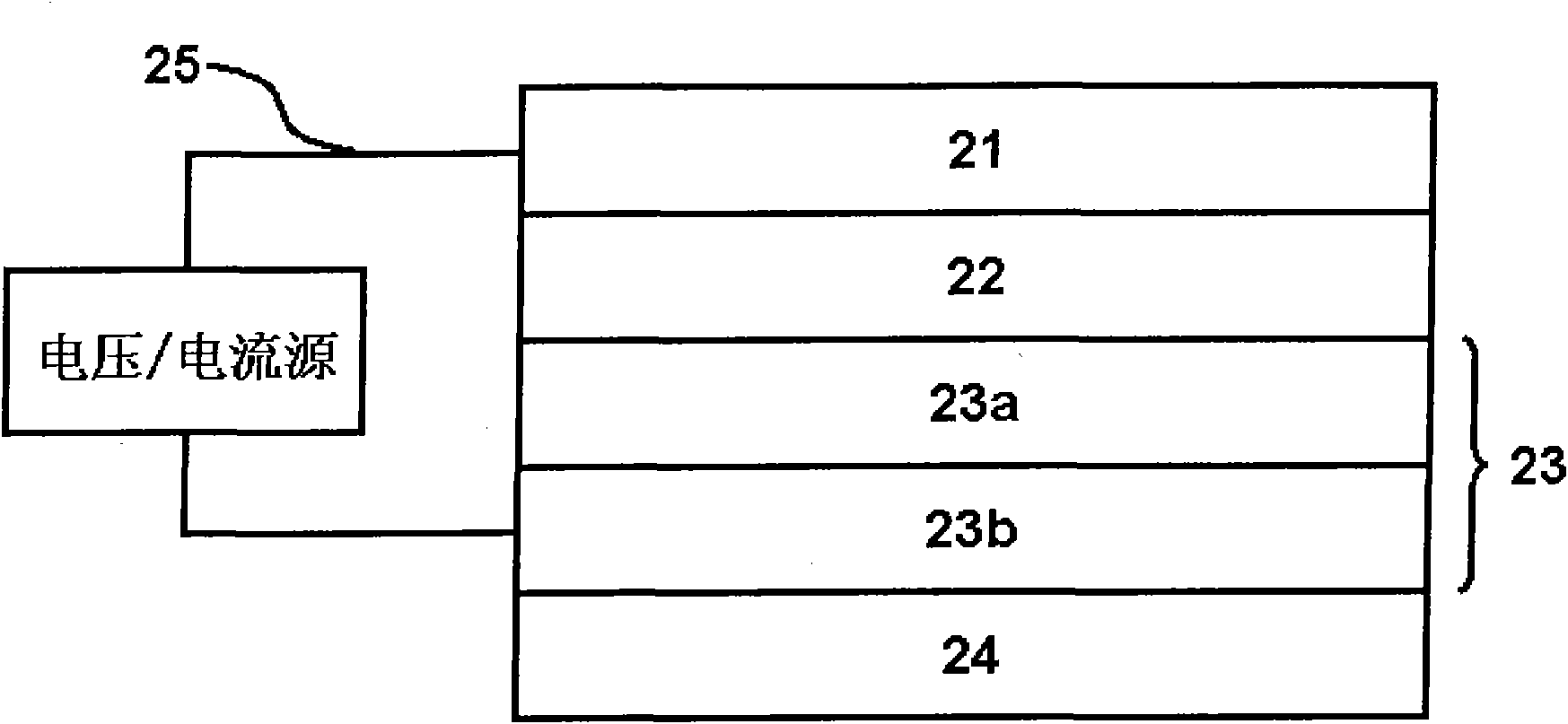
[0031] see figure 2, the organic electroluminescent device has three structural layers: an anode 23, an organic electroluminescent layer 22 and a cathode 21; their structural relationship is that the organic electroluminescent layer 22 is between the anode 23 and the cathode 21. The anode 23 of the device is composed of two parts: a metal aluminum layer 23b and a molybdenum oxide (MoOx) 23a layer, wherein the molybdenum oxide (MoOx) 23a is between the metal aluminum layer 23b and the organic electroluminescence layer 22 . The thickness of the metal aluminum layer 23b is selected between 0.1nm and 200nm; the thickness of the molybdenum oxide layer 23a formed on the metal aluminum layer 23b is between 0.1nm and 5000nm. The structural formula of molybdenum oxide in the molybdenum oxide layer 23a is MoOx, wherein the value of x is between 2 and 3, and the value of x can be equal to 2 or 3. The organic electroluminescent layer 22 is sequentially formed on the molybdenum oxide lay...

Embodiment 2

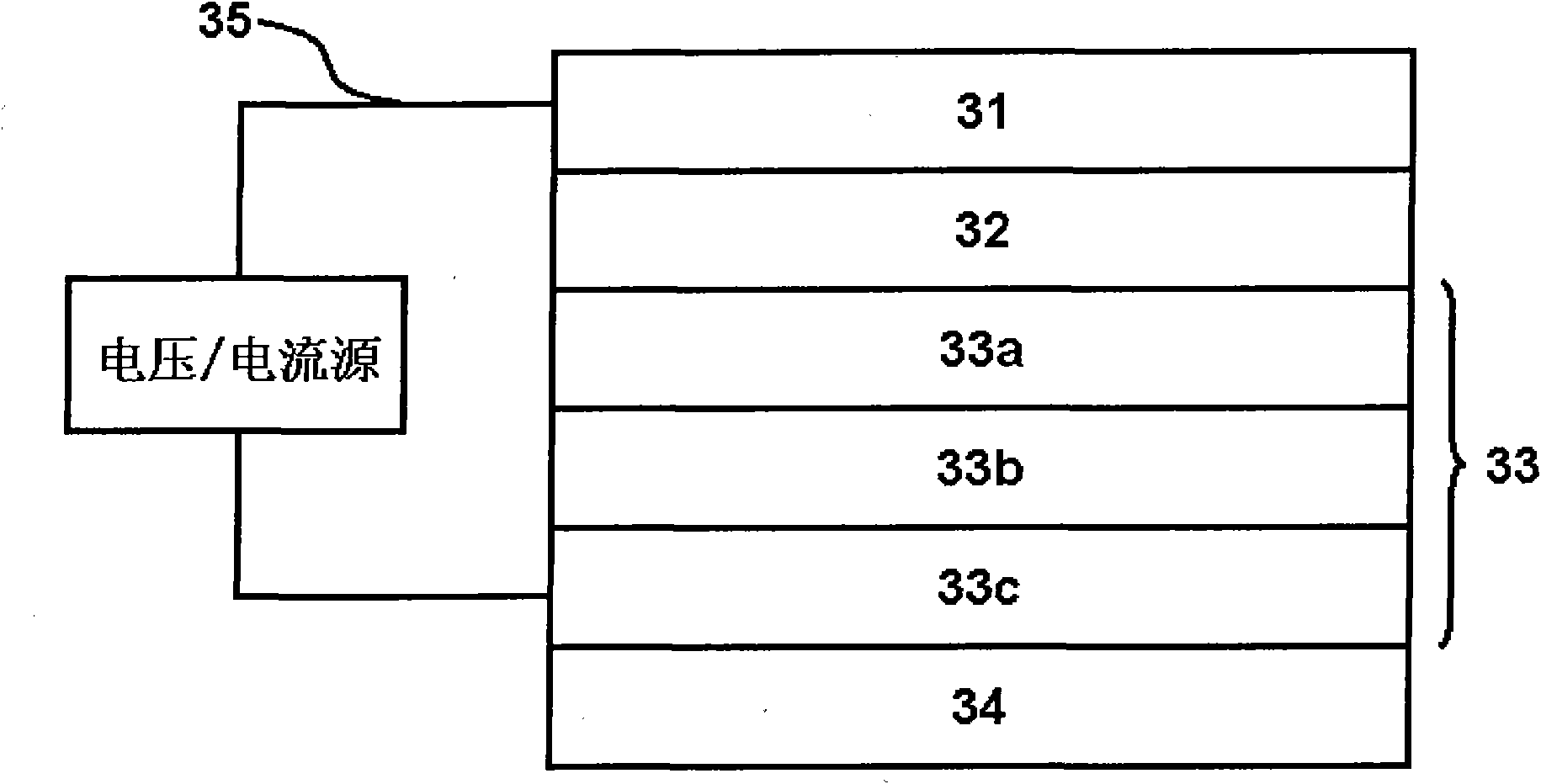
[0035] see image 3 , the organic electroluminescent device has three structural layers: an anode 33 , an organic electroluminescent layer 32 and a cathode 31 ; their structural relationship is that the organic electroluminescent layer 32 is between the anode 33 and the cathode 31 . The anode 33 of the device is composed of three parts: a molybdenum oxide layer 33a, a metal aluminum layer 33b, and a multilayer metal layer 33c. The organic electroluminescent layer 32 is sequentially formed on the molybdenum oxide layer 33 a , and the cathode 31 is formed on the organic electroluminescent layer 32 . The thickness of the molybdenum oxide layer 33a is between 0.1nm and 5000nm; the thickness of the metal aluminum layer 33b is between 0.1nm and 200nm; the thickness of the multilayer metal layer 33c is between 0.1nm and 200nm. The structural formula of molybdenum oxide in the molybdenum oxide layer 33a is MoOx, wherein the value of x is between 2 and 3, and the value of x can be equ...


PUM

PropertyMeasurementUnit
Thicknessaaaaaaaaaa
Thicknessaaaaaaaaaa

Abstract

The invention relates to an organic electroluminescent diode apparatus, which comprises an anode, a cathode and an organic electroluminescent layer formed between the anode and the cathode. The organic electroluminescent diode apparatus is characterized in that: the anode has a double-layer structure, which comprises a metal aluminum layer and a molybdenum oxide layer; light produced by the organic electroluminescent layer is emitted from one side of the anode; the anode is taken as a light-transmitting layer; and the cathode is taken as a light-tight reflecting layer. The invention provides an anode for replacing indium tin oxide (ITO) and the organic electroluminescent diode apparatus which emits light from one side of the anode. Compared with the ITO, the anode has the advantage of low price, solves the problem that elemental composition (the ratio of elements, such as In, Sn and O) of the ITO is difficult to control in a membrane forming process, and keeps high light transmittance and excellent current carrier transmission and injection performance; and the preparation process of the anode is simplified and the manufacturing cost is reduced. Light produced by the organic electroluminescent diode apparatus is emitted from one side of the anode, so the defect of too fast performance aging of an apparatus which emits light from one side of the cathode can be overcome.

Description

technical field [0001] The invention relates to a photoelectric device, specifically an organic electroluminescent diode device. technical background [0002] The basic structure of an organic electroluminescent device is an anode, a cathode, and an organic light-emitting layer placed between the anode and the cathode; holes are injected into the organic light-emitting layer through the anode, electrons are injected into the organic light-emitting layer from the cathode, and the organic light-emitting layer is excited. The luminescent substance produces light emission. Organic electroluminescent devices are currently used in flat panel displays and lighting. For the application of flat panel displays, organic electroluminescent technology has many advantages such as light and thin, simple structure, simple manufacturing process, low power consumption, and excellent color expression; for lighting applications, organic electroluminescent technology has low power consumption. ...

Claims


Application Information

Patent Timeline
IPC IPC(8): H01L51/50H01L51/52H01L51/54H01L51/56
CPCH01L51/5215H10K50/816
Inventor 苏璇
Owner 苏璇
Learn More