Split-phase compensation self-healing type reactive compensation capacitor

A technology of compensating capacitors and phase-splitting compensation, which is applied in reactive power compensation, reactive power adjustment/elimination/compensation, etc., can solve problems such as ineffective compensation, damage to lines and equipment, unbalanced three-phase loads, etc., to achieve Good phase compensation ability, saving space and reducing line loss

Inactive Publication Date: 2010-09-22
巨华(广东)电气有限公司
View PDF5 Cites 4 Cited by
  • Summary
  • Abstract
  • Description
  • Claims
  • Application Information

AI Technical Summary

Problems solved by technology

However, when the three-phase circuit is unbalanced, it can only ensure that one of the three phases is in the best compensation state, but does not ensure the compensation effect of the other two phases, which will easily cause over-compensation or under-compensation, and cause over-compensation in the line. The condition of voltage or high current will cause damage to the circuit and equipment. During operation, when one phase is damaged, the other two phases are still running, which will easily cause the capacitor to explode or damage the equipment.
[0004] Especially in civil buildings, because civil buildings use a large number of single-phase loads, it is easy to cause serious unbalance of three-phase loads, because the sampling signal for compensating reactive power is taken from any of the three phases, resulting in unsampled The other two phases are either overcompensated or undercompensated
If it is overcompensated, the voltage of the overcompensated phase will increase, which will easily cause damage to electrical equipment such as control and protection components due to overvoltage; if it is undercompensated, the current of the compensated phase will increase, and equipment such as lines and circuit breakers will be damaged by the current The increase causes the heat to be burned out
Therefore, the traditional three-phase reactive power compensation method cannot be used

Method used


Image

  • Split-phase compensation self-healing type reactive compensation capacitor
  • Split-phase compensation self-healing type reactive compensation capacitor

Examples


Embodiment Construction

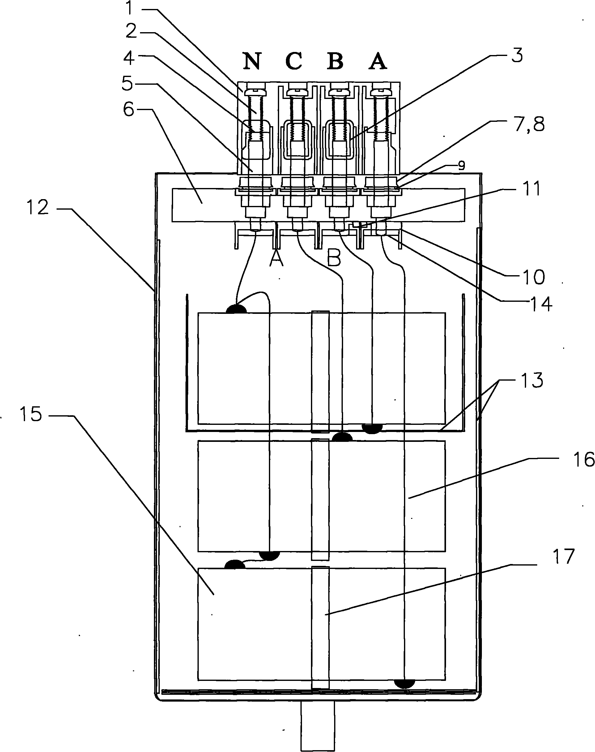
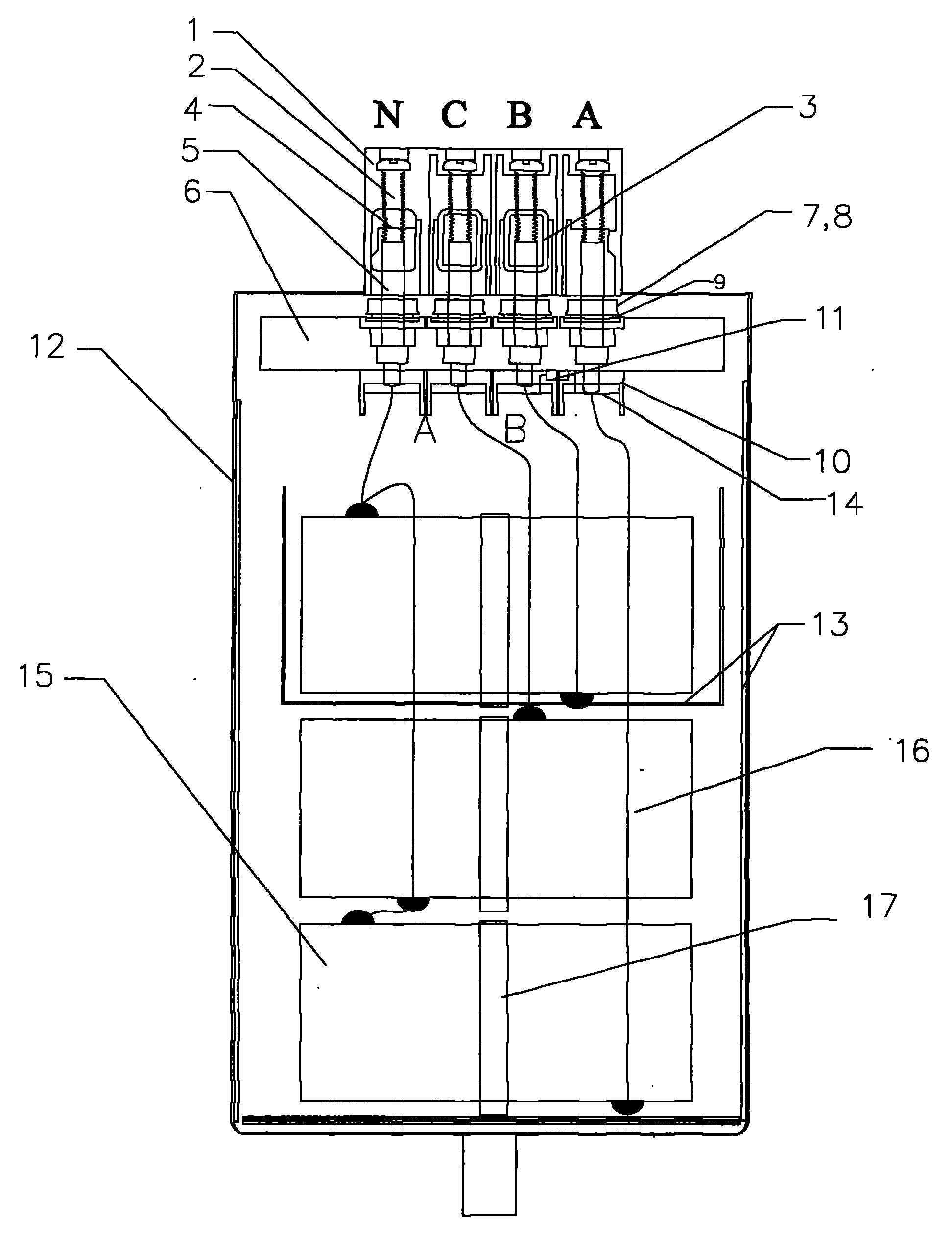
[0014] Such as figure 1 As shown, in the phase-splitting compensation self-healing low-voltage reactive power compensation capacitor, the capacitor shell 12 is an aluminum shell with fast heat dissipation and good dense performance, with terminals on the top, and a heat-resistant plastic terminal cover 1 on the terminals, which can effectively It separates the phases and plays the role of arc prevention. There are four copper pillars 5 on the terminal, which can pass a relatively high current and have good energy conduction performance. The capacitor adopts a pneumatic protection device. The iron plate 6 is one of the important components of the capacitor protection device, which can effectively protect the capacitor and Device security. The copper column 5 is inserted into the iron middle plate 6 and enters into the aluminum shell of the capacitor. The copper column 5 is pressed onto the top of the iron middle plate 6 to fit the lug 4, the square screw 3 and the movable loc...


PUM


Abstract

The invention discloses a split-phase compensation self-healing type reactive compensation capacitor comprising a capacitor shell, four connecting terminals, a connecting wire and a metallized thin film, wherein the connecting terminals and the metallized thin film are connected by the connecting wire, potting materials are filled in the capacitor shells, the connecting terminals comprise three three-phase connecting terminals and one neutral-point connecting terminal, and the connecting mode of the capacitor is in a three-phase and four-wire Y connecting mode; a plastic base is arranged in the capacitor shell, the terminals are provided with four copper cylinders, cooper sheets are arranged under the copper cylinders; the bottom of the capacitor shell is provided with a film rolling axis, and the metalized thin film is a polypropylene metalized thin film which is winded on the axis. The invention has functions of compensation and distribution. The required capacitance for each phase can be input respectively, so that the reactive compensation of each phase achieves the optimum state, which has an obvious effect on improving the power factor of a power grid, improving the efficiency of the power grid, reducing line loss, improving voltage quality, reducing electricity consumption, increasing the active capacity of a transformer, reducing distribution cost, and saving space.

Description

technical field [0001] The invention relates to the technical field of electrical components, and more specifically relates to a phase-splitting compensation self-healing low-voltage reactive power compensation capacitor. Background technique [0002] The role of the reactive power compensation device in the electronic power supply system is to improve the power factor of the power grid, reduce the loss of power supply transformers and transmission lines, improve power supply efficiency, improve the power supply environment, and meet the requirements of the power grid load terminal voltage level and economic operation. Therefore, the reactive power compensation device is in an indispensable and very important position in the power supply system. Reasonable selection of compensation devices can reduce the transmission of reactive power, thereby reducing voltage drop, minimizing network loss, improving power grid quality, and having good economic effects. Conversely, if it is...

Claims


Application Information

Patent Timeline
Patent Type & Authority Applications(China)
IPC IPC(8): H02J3/18
CPCY02E40/30
Inventor 何锦鹏
Owner 巨华(广东)电气有限公司
Why Eureka
Try Eureka